Randy Roberts' photo-essay on visualizing stiffness: another tool for understanding bracing [Pictures] - created 09-09-2010
Roberts, Randy - 09/09/2010.22:18:48
May your life's music always come from your heart.
As demonstrated on MIMF over the years, there are a host of methods of trying to analyse and understand acoustic guitar tops and bracing: tap tuning, flexing, Chladni patterns, finite element analysis (FEA), etc.
As an amateur building 1 or 2 a year, I will never have the opportunity of gaining the experience of tapping and flexing hundreds of tops, (and cant retain a usable memory 9 months later of what the last top sounded and felt like). FEA and other software approaches are beyond my understanding. Ive been playing with Chladni patterns for several years, and understand (I think) what the tea leaves are trying to tell me, but have found it extremely difficult to truly visualize what the patterns are reflecting as to the distribution of stiffness in the tops.
At the Healdsburg Festival a while back (and in his excellent 2 volume book) Irvin Somogyi presented a model of typical Martin braced top that showed the true stiffness of the bracing based on the fact of the stiffness is the cube of the height of the brace.That one moment of actually seeing stiffness had a profound effect at the time, but the image has just been floating in the back of my mind until recently.
Ive been trying to work my current projects top to what I thought was a pretty even gradient of stiffness, but not making much headway for all the time invested.
Heres the top in question

I was having my usual difficulty figuring out what to do with the Chladni patterns I was getting, when Irvins model came to mind. why not model this top and see if that would help grasp what was going on.

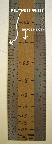
I made a spreadsheet that calculated the stiffness for every 0.05 inch of brace height. I divided this by the top thickness to derive the scale of brace height to actual stiffness. (After getting sick and tired of going back and forth from brace to spreadsheet, I wised up and just put the proportion scale on a ruler, and this made actually using the data very simple).
I traced the profile of each brace onto a 0.1inch grid graph paper (graph paper glued to clear plastic allowed tracing with fine point permanent marker, which cleans off with alcohol).

From the tracing I converted the height of the brace to stiffness, and plotted that on another sheet of graph paper.

This alone let me see a number of things about the stiffness of the current bracing, but in a view distorted from reality, as all the braces are depicted parallel to each other, not as they are actually oriented on the real top.

To create the actual model, I just laid the stiffness plot over a sheet of balsa wood and poked holes with a mechanical pencil along the stiffness plot into the balsa and cut out each brace.
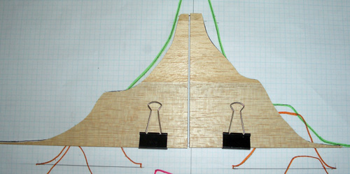
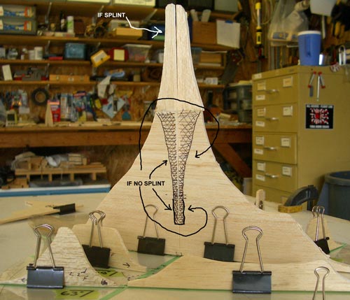
Setting these on top of the bracing pattern template gives an accurate model of the stiffness distribution of the current bracing.

This model makes obvious a number of things that I simply cannot see looking at the braced top itself. One example is the difference in stiffness that results from splinting across the gap where the X braces cross, vs. not splinting that gap. I obviously want to splint the gap, but from the dramatically distorted junction stiffness, I obviously dont need the junction of the x braces to be as high as it is.
Neither the upper nor lower arms of the X are balanced stiffnesswise with each other. I really don't see this difference when looking at the braces themselves.

Comparing the X arms and finger braces on the left vs. on the right show a marked difference in both stiffness, and in the smoothness in transition of the stiffness from center radially out to the sides.
Left finger braces.

Right finger braces.

It dawned on me while doing this that where this might have the most usefulness is in when designing a new bracing pattern in the first place. Basically you could just reverse the above steps. You could start out with a model of what you the want the stiffness pattern to be, and then work backward to end up with the profile on the braces that will result in the stiffness pattern you want.
Maybe this is obvious to you guys or you can see this just looking at the bracing, or by tapping, or flexing. But its been kind of a revelation for me.
I wanted to throw this method out there to see what your thoughts about its potential might be.
Holy crap, Randy, that is frickin' brilliant!
So, I think the next step would be to do your 3D analysis on some exemplary tops to find out what sort of stiffness is actually desirable. (Your braces end up looking like the Tetons. Do "good" tops look like mountains, or rolling plains?) Then, one could conceivably create a template for that stiffness distribution.
I'm no engineer by far, but I'm guessing that this would all be rather approximate, getting you in the zone, but not giving you final dimensions. After all, different densities would give different results. And brace positioning would be crucial, right? Maybe there is some math that could be done to factor in average material densities.
Way cool, man.
Wow, that seems like a lot of work but it looks cool!
Just one thing, it seems you have modeled the braces individually and then superimposed them. I'm no engineer but I don't think you can just interpolate between the balsa pieces to get a stiffness model for the whole top (if that is what your aim is). There's probably some more complicated calculations to get the bits in between the braces as I am guessing that is not a simple linear function.
In any case, it definitely helps to see how much each of the braces contributes to the top stiffness. Good work!
Randy, I took Somogyi's week long voicing class a few years ago and we did this exact same exercise in his shop. We used foam posterboard to construct our models. It is eye-opening for sure.
My biggest take-away lesson was that a slight change in brace height makes a huge difference in stiffness. So when I am nearing the final brace height during carving, I try to remove very thin slices with a finely set fingerplane to sneak up on the optimum. Using a chisel during the final carving is too crude of a tool and may cause you to overshoot the optimum and end up in the floppy zone.
One thing I don't understand is your photo of the ruler. I can't get the math to work out right. Can you explain that one, please?
This is also explained in Somogyi's book. Nice reproduction, though, for your own braces. It's a great way to understand stiffness, and a lot of trouble. Thanks for posting, as your explanation is easier to understand, somehow!
Randy; beautiful and simply ingenius!! Reminds me ever so slightly of making mountain 'shells' in styrene for model railways!
An open question.....would it not be more representitive to include the 'shear' stiffness of the sides, or is this presumed? And...in general terms, as I imagine this is relatively accurate, is not the bridge/saddle position far too stiff??
Excellent representation.
I was having my usual difficulty figuring out what to do with the Chladni patterns I was getting, when Irvins model came to mind. why not model this top and see if that would help grasp what was going on.
Randy, did your model help you make sense of the Chladni patterns?
How do you use your model to help you build?
John
I'll take a stab at that last question because I have built three guitars after making my stiffness model.
The model in Randy's photo indicates areas of excessive stiffness. The x-brace joint is obviously overly stiff. One can thin the x-braces and lower them in height considerably, without weakening the area too much. The bridge and bridge plate also stiffen up this area a lot which is not represented in the model for purposes of simplification. So there is much room for lightening up on the x-brace joint.
Other areas than could be loosened up include the finger braces. They appear to stiffen the sides of the top too much in Randy's example, in my opinion.
Also, the x-brace and tone bar scallops causes fairly severe differences in stiffness along the length. There are builders who like this approach, but I have taken a different path and taper the x-braces smoothly without scallops, which leads to a uniformly vibrating brace instead of one with non-uniform characteristics.
First: there's nothing wrong with that 'ring+' mode Chladni pattern: it's hard to get it to close when the bracing is asymmetric.
I have to wonder if including the stiffness of the plate itself would buffer the results so to speak. It might be hard to take into account the difference between long-grain and cross-grain stiffness.
Mass distribution also makes a difference in the vibration, of course, and tends to counter some of the added stiffness of taller braces. Again, a buffer of sorts.
None of which is meant as a criticism: it's always useful to do these sorts of simple models that help us visualize what's going on. We do it too seldom, and share even more rarely. Thanks.
Alan Carruth / Luthier
I do want to make two things perfectly clear:
1. I DONT, IN ANY WAY CLAIM THIS WAS MY IDEA. Not having had the good fortune of taking Irvin Somogyis class, I was un-aware this technique was used by him or others. But, as I said in the first post, I saw Irvins stiffness model of a Martin braced top at his Healdsburg lecture, and (I believe the same top) in his book. At the lecture it was shown to demonstrate, rather critically, what sounded to me to be faults of that top. I said that Ervins model had stuck in my mind and had come back to me while working on this top. Looking at brace stiffness this way is Irvin Somogyis genius, certainly not mine.
(I did however realize it was urgent that my wife see your comments. She was singularly unimpressed however, and muttered something about having your heads examined. In her defense, she has had an awful lot of Chladni Muzak music the past several weeks.)
2. This thread wasnt originally posted as any sort of tutorial. The title has been changed by the staff from the original. I posted this as a question, wondering what you might see as pros or cons to looking at braces this way. Comments here by me should not be seen as coming from a knowledgeable source. If they are seen as coming from a hobby Bozo making 1 or 2 guitars a year while sharing his shop with a 01 Camry blowing blue smoke, and an underutilized lawn mower, you should be safe.
Jason,
Id love to do what you suggest with exemplary tops. I am in the middle of what both coasts consider as nowhere. The only tops I have are mine and they are not exemplary. Id also love to know if I want mountains or rolling plains. My guess is rolling plains.
Chuk,
I dont see this as actually modeling the whole top attached to the body, but as just a way of seeing brace stiffness. I think Chladni patterns may be better for seeing the whole top as a unit, again as a free plate, not attached to the sides. I agree the stiffness doesnt stop at the edge of the brace, but is instead shared in some way outwards from the brace, I dont have a clue as to in what manner. Maybe its out at a 45 degree angle from the top of the brace, like the pressure from a clamp out through whatever cauls is between the clamp and the workpiece? I think its more likely by some geometric decrease in stiffness with distance from the brace, if for no other reason than nothing seems to be simple.
Barry,
Boy, no kidding! Also true with the Chladni patterns. As you get closer to what youre wanting it doesnt take much to change things a lot.
As to the ruler, to derive the stiffness, I did the following:
[ ( brace height + top thickness) cubed / top thickness cubed ] X 60% (triangular braces)
This gave me a range of 0.1 height = 6.5 stiffness factor to 0.75 height = 564.6 stiffness factor
As this range would result in a 6 foot high model, I then divided each stiffness factor by 75 to bring the range of the scale down to fit on graph paper. Im seeing this last division by 75 ( or any other amount) as basically just a volume knob for the Y axis. Im just turning down the volume on the height of the model. This is what I then put on the ruler. The scale will vary with where you set the volume to fit the scale you need.
Waddy,
I know Irvins picture of the Martin top is in his book, but where does he discuss using this kind of modeling anywhere? Please let me know, because I would consider that priceless in trying to use this. Please let me know.
Kif,
I dont think the sides factor in here. This is a static depiction of the brace stiffness. You could model the sides if you wanted but if a 4 side were scaled to these braces stiffness scale, the sides would be 67.6 feet high.
John,
I think its helped me see the why of the Chladni patterns more clearly. Unfortunately its also causing to doubt things I thought I knew. I keep reminding myself that this is a picture of the top, the Chladni patterns are a picture of the top, Tap tuning is a picture of the top. You get a lot of information from a picture, but a picture of a sailboat is not a sailboat.
I havent used this yet to design bracing, that was why I originally posted it was to gather info on how valid it might be for planning out the braces of the next one. As it stands now I foresee this model probably being used as the reason I brace this top for the fourth time about a month from now when Ive destroyed it again .
Alan,
theres nothing wrong with the ring and a half mode
Then I guess Im bothered by why the mode would look ok with such a stiff X junction, etc. does the ring and a half mean Ive compensated for that stiffness elsewhere in the top, or does the Chladni pattern technique not catch this excessive stiffness? Im starting to doubt things I thought I understood.
One corncern I have with this model is the fact that it in no way accounts for the fact that the stiffness of the brace is also decreasing (again, as the cube, and so should be as significant as the cube of the height) based on the lenghth of span, just like a floor joist. I've found no way to wrap my head around that one.
Hi Randy,
It would be interesting if you could map out the distribution of the forces acting on the top. My guess is that it would make the X brace size look much less excessive.
Interesting modeling.
Here's an idea: so you don't have any "exemplary" tops to measure and model, so what. Mock up a couple topographic models that make intuitive sense, and then translate that into brace profiles. It'd be interesting to find out what those tops look and sound like, and how closely they actually compare to "typical" brace patterns and profiles.
Rolling plains is right on the money. Mountains just block the view.
But then again, from where I sit even rolling plains is a helluva a lot of elevation!
Randy Roberts wrote:
"Then I guess Im bothered by why the mode would look ok with such a stiff X junction, etc. does the ring and a half mean Ive compensated for that stiffness elsewhere in the top, or does the Chladni pattern technique not catch this excessive stiffness? "
Each Chladni pattern is a sort of snapshot of the stiffness and mass distribution in the top from one point of view, as it were. In the case of the 'ring+' mode the X crossing is in an area where there's not a lot of either bending or motion going on, so fairly large changs in the stiffness and mass there don't show up as big changes in the mode shape or frequency.
As it happens, the X junction doesn't move or bend a lot at the pitch of the 'main top ' resonant mode either, and that's the main sound producer on the guitar. The high stiffness at that point seems to be more important structurally than acoustically, so you might not get a lot of tonal return from reducing it, and the structural cost could be high. If there's any rationale for paying so much attention to the 'ring+' it's because it mimics the 'main top' mode so closely. Intuitively it seems as though getting the one 'right' would facilitate the other, but that's awfully hard to justify in any 'scientific' sense.
The 'T' mode, usually the second mode if you count up from the lower pitches, will be effected by the stiffness of the brace crossing. It's a 'torsion' mode, with the corners twisting up and down, and, curiously, no bending hapening at all, at least in the ideal case. X bracing adds a lot of torsional stiffness. The thing is that I don't think anybody has looked at that mode to see if it's a predictor of good sound.
Which makes the point that we're sort of at the beginings of using Chladni patterns as tools for working on guitar tops. That means that there's plenty to be learned about it. Usually we find smething out through a disaster of one sort or another: a guitar that 'should' have sounded fine came out lousy, and, on going back through the records, we find something 'different' that can be used as an indicator of the problem.
Somehow it never seems to work the other way: the 'great' ones don't often have some clear marker of greatness, alas. Or maybe they do, but we're hobbled by a paucity of data. Perhaps when I've made 50 that I consider to be 'great' I'll have a better idea. Stay tuned...
Alan Carruth / Luthier
I really like the visual impact of your 3-D model here. Is there a way to make the same type of model, but include the top with it, as well as brace location?
The stiffest braces in the world will still result in a "loose" top that can fail or belly badly, or sound "muddy/lacking focus", and the lightest structurally sound bracing can still yield a overly stiff top that will sound "tight/restrained/nasely", depending very much on the brace layout. If you can somehow tie your brace models with top stiffness and brace layout/location, wow...
Randy; thanks for the side height..just puts things in perspective in a way that makes sense to me! 69.5' might give better bass response!!!!!
Randy, in Somogyi's course, the stiffness model was strictly used as a visualization exercise to get one thinking about the cube rule. It was in no way used as a tool for designing bracing patterns.
Alan,
Mario,
yes, no, and maybe? As I've run ideas through my mind, I always end up with the problem of scale.
4 possibilities?:
1. Assume a uniform stiffness of top, which actually post #8 demonstrates what you would get. I lost the stiffness data for this top so I just ignored reality and assumed it was the same stiffness as the brace wood. (about 480,000 PSIA/(gm/cubic cm.)but that is neither here nor there as the brace model is relative to itself only)
A 0.10 thick top would result in a stiffness scaled to these model braces of 0.018, which is just a little more than the thickness of the mylar template the brace model sits on. This obviously isn't of any use to you in modeling the whole top and braces. Big differences in graduating the top would still be imperceptible to the eye in this scale.
2. Use some method (perhaps David Hurd's deflection testing?) to map the stiffness of the unbraced top, or if mapping out thickness across the top, turn up the "volume knob" in the spreadsheet (divide each of these stiffness factor results by a number smaller than the 75 i used in this model)so that the variations in stiffness show up more noticably. Then stick on braces scaled to this same "volume" onto the top model. The problem with this is the sameas in 1., only now your braces are sky high. I can't think of a way to model two such disparate stiffness ranges in one model.
3. Use two different systems to get a composite image of the whole.
I'm picturing one of those old stereoscope things, with paired pictures of the same scene taken from slightly different angles that result in a 3-D image when you look through them.
On one side of your mental stereoscope, you put your brace stiffness model picture. In the other side you put another picture of the top, say flexing, or deflection testing, or tap tuning, or, gasp!, Chladni patterns (I'm sorry Mario, I just couldn't resist
It's still not a sailboat, but now it's at least a 3-D picture of a sailboat.
4. Now if someone could recreate on the computer, an accurate software model of this, and figure out a way for it all to somehow show up visually, then you could factor all of these other variables for the top stiffness: top and brace stiffness, "shared" stiffness out from the brace, brace length, brace positions, etc., into one model........
I think we need to bait someone like John Platko into unwittingly committing himself to this, don't you? I mean, if you can't model this subset of factors of a guitar, how can you model the whole guitar. (How's that for a nice treble hook?
I think what I'm probably going to try to do is put the brace stiffness model in one side of the old stereo opticon, and then Chladni analysis in the other side, as those are the tools I have readily available. But I think as far as a Grand Unified Theory, I don't think this is it.
Randy: Don't think Ervin had the idea of working backwards from a model. I think he would be very happy that you expanded on his idea.Hope someone can work this further and maybe we can see some end result and push our knowledge a bit further down the road. Think this post also helps to answer the question are Somogyi's books worthwhile. When it leads to thinking like this the answer is a resounding YES. Nice work Randy congrats to you...!!!!
Tom
I think we need to bait someone like John Platko into unwittingly committing himself to this, don't you? I mean, if you can't model this subset of factors of a guitar, how can you model the whole guitar. (How's that for a nice treble hook?
Randy, the reason I'm going down the FEA path is that the guitar structure is so complicated that coming up with an accurate intuitive model for even the static forces is no easy task. In fact, I've come to the conclusion that even having a very accurate model of the top with all its accoutrements can be misleading so I want to start understating the details of top displacement with a model of a complete guitar. When the model matches what I see on actual guitars I'll work to simplify the model.
I don't want to discourage you though, it would be pretty hard for someone to forget how stiffness increases with the cube of the height after seeing your model. And it's an important thing to know. So I think it's great.
Unfortunately it's only one variable and the others are important too. Equally important to the height of the beam is the length of the span, which also effects the displacement by a cube. I imagine that if you added the length of span effect to your stiffness model that things might smooth out some- but don't ask me exactly how.
David Hurd's book gives a model for averaging the orthotropic Es into a single number, that might help you add top stiffness to your brace model, but I'm not sure that that would tell you. And don't forget the bridge and bridge plate.
From various FEA experiments I've found that it's important to use accurate string force vectors to see how the top displaces, otherwise you're chasing things that the guitar will never see- unless you plane to sit on it.
Also, resonance is an odd duck so it's hard to go from a simple model to mode patterns. The frequency of modes though has a SQUARE ROOT(stiffness/mass) relationship and that has a big "smoothing" effect on how the stiffness peaks in your model end up effecting resonance. You have to loose a lot of stiffness to make the resonant frequency that is being effected by it change a lot in frequency.
I would be curious to hear what Ervin tells folks to do with this model. Anyone want to spill the beans?
John
Recovered posts that were lost in the server crash:
Alain Bieber - 03:24am Sep 15, 2010 EST (#46 of 50)
Brad,
As a general rule, I do not participate in discussions dealing with steel string guitars. Not by lack of interest but because I have absolutely no experience in that.
Your last post raises a point of general interest in the design of all musical instruments. Would what you call a prescriptive model (similar to what I called a unified theory in the thread on big versus small guitars still visible here) produce an "ideal" sound that would be so superior.. that it would impose itself as the one and only type of guitar type ??
The question can be treated as a negligible one on the ground of many logics a/ beauty in sound is not unique b/ guitars should be adapted to each répertoire of a good musician c/ never an historically admired instrument has not been replaced by another one.. you can add to the list of course.
But in spite of all such arguments dealing with the warranted "bio diversity", so to speak, of musical instruments, my hunches are that there is a risk (more for classical guitars than for "folk" ones) that a more uniform style of sound could be brought by the wings of scientific and economic thinking. I often quote the Steinway example.
I fear that even the artistic nature of music is not enough to protect against a philosophy of "ideality". But acoustics knowledge being what it is, it will take some time to see that occur. Not in our lifetime
And, like you, I do not think Randy is running after a tool of such an imperious nature.
--------------------------------------------------------------------------------
Barry Daniels - 09:14am Sep 15, 2010 EST (#47 of 50)
MIMForum Staff
John, but those claims were my own, not Somogyi's, which is what you were demanding to know.
It's just that for a big buck luthier book I would hope that in addition to a visual of the effect of height on stiffness you would also get an explanation of what to do with the information.
Ervin teaches people that brace stiffness goes up with the cube of the height. Then, what does he teach them to do with that information?
It is trollish to switch the subject of your argument around like that.
--------------------------------------------------------------------------------
Waddy Thomson - 10:17am Sep 15, 2010 EST (#48 of 50)
Ervin teaches people that brace stiffness goes up with the cube of the height. Then, what does he teach them to do with that information?
That's the whole point. He doesn't tell anyone how to use it. His goal is to get them to find out how to use it. He changes the way you think about the build, and never tells how to do it. His point, as I have seen stated, is that if he tells people how to do it, you'll never really learn "how" to do it. Sort of the "teaching a man to fish" philosophy. You can teach a person how to fish, but you cannot teach a person how to "catch". Otherwise, they would call it "catching".
--------------------------------------------------------------------------------
Greg Robinson - 11:29am Sep 15, 2010 EST (#49 of 50)
Blaquanun!
Haha, Waddy, I've always heard that as:
"You can give a man a fish, & he eats tonight, or you can teach a man to fish, & he eats for a lifetime."
--------------------------------------------------------------------------------
Mario Proulx - 11:37am Sep 15, 2010 EST (#50 of 50)
Hear the colors....
That's the whole point. He doesn't tell anyone how to use it. His goal is to get them to find out how to use it. He changes the way you think about the build, and never tells how to do it. His point, as I have seen stated, is that if he tells people how to do it, you'll never really learn "how" to do it. Sort of the "teaching a man to fish" philosophy. You can teach a person how to fish, but you cannot teach a person how to "catch". Otherwise, they would call it "catching".
Exactly. What. I. Always. Try. To. Do.
There is no -one- formula to building a great instrument, so if we hold your hand and spoon fed everything to y'all on how to build a great (name your favorite style here) guitar(which would include you sending up the woods so we could judge them and make our recommendations), all we've accomplished is to get you to build -one- guitar. But if we can somehow get y'all to pull your heads out of the sand and breath some air for a bit and begin to make y'all -think- like we do, then you have a chance at grasping how to build great instruments, no matter the shape/size/type.
A lot of science has been thrown at studying the finest violins of the world, yet science hasn't found the answers. All the great ones have been created by, well... Great Luthiers! It's only by trying to get your mind wrapped around theirs that we can move forward. The mechanics of an instrument are rather simple; it's the thinking behind how to manipulate the mechanics, and the finest details within those mechanics, that holds the answer.
In other words, stop thinking like a roof truss designer, and start thinking like a luthier.
Randy, again, a great visualization tool. If I may suggest a way to make it 'work' for your guitar? Keep the model, and after stringing up the guitar, make notes of its tone, response, everything. And make good notes of any distortion you see on the top. Note how much the top raised when you initially strung it, etc... Then with the passing of time, stop and write down, without looking at the original notes, what your hear in the tone, response, etc..., and again, study that top, measure the distortion, etc... Now compare the notes. If you see a pattern developing , such as "the tone is getting less focused, sounds like it has old strings on it all the time" and you also see the top distorting too much here, and not at all there, then on your next guitar, try to adjust the peaks to stiffen the weak area, and at the same time, look at where you might be able to take some height off. Then make a new model of the new braces, and compare them to the older model. I'd be very interested to see where you "push" the bracing using such a method, and I bet you'll learn a ton, on your own, while doing it. Most of us likely do this by instinct, and this is where being a repairman first, where having many old, great instruments pass through our hands, helps a lot and shortens the learning curve(if we're open to learning, that is). But there's nothing wrong with using this visual model to help, and I'm even curious to see how my typical braces would look, as well as see how they've evolved over the past 14 or so years! Keep at it; you're on the right path.
Hi Randy,
Clay,
I'm not picturing what forces you are speaking of, nor seeing how a static model would lend itself to this if you are talking about dynamic forces. Would you mind elaborating?
Hi Randy,
Your model gives a visual amplification of the brace stiffness. If a similar model could be created of the static forces acting on the soundboard it might provide a basis for evaluating the soundness of a bracing scheme. It may show the areas where you need more structure as well as areas that are overbraced.
Clay Scheaffer wrote:
" I have found that a principal point of failure on old and often improperly strung guitars is in the area between the soundhole and the bridge."
I've always thought of that as the most critical structural area as well, where compression along the grain and bridge torque combine to produce a buckled in dish. The two most successful bracing systems for flat tops, the so-called 'Torres fan' and x-bracing, both concentrate wood in that area. There has to be a reason.
Alan Carruth / Luthier
Alan, Randy, and all those with an interest..
Though I entirely share your feeling that the two strutting reference models ( Spanish fan for nylon, X brace for steel) will continue to represent in the future the pillars on which one shall build if looking for very good sounding instruments, I note with interest bolder attempts to diversify in the recent past.
New forms of strutting (such as lattice) meet success but, and that excites me even more (when I am in an innovative mood
I would tend to think that now we can assert that such "plate innovations" are important, and here to stay, but I accept debates and contradiction...
Maybe this discussion would need another thread? If worthwhile?
My take on sandwich tops is that you're making a lower density 'synthetic wood' in a sense. I've messed with that a bit, and the sandwich layup seems to work like the wood in the skin, but it's stiffer for the weight. Aren't most sandwich tops braced more or less normally?
Lattice bracing could be viewed in somewhat the same way, or as a simple matter of using more braces that are narrower and closer together, depending on your point of view. One of my former students has done some work with a 'fanned lattice': the lattice elements are not parallel in either direction, but converge like fan bracing. This puts more bracing between the bridge and soundhole.
If you poke around in the dusty corners of lutherie long enough you can find all sorts of experiments. Most of them didn't work out very well, of course, which is why you never hear of them, and why people keep repeating them. Some ideas, like lattice bracing and sandwich constrruction, do show a lot of promise, but I think it will be a while before they're fully developed. Then we'll see if they take over the world.
Alan Carruth / Luthier