Andreas Barth's '62 Bandmaster and Blonde alnico 2 pickup guitar [Pictures] - created 10-19-2010
Barth, Andreas - 10/19/2010.18:18:59
MIMForum Staff
I had the good fortune of stumbling across this amp in a London Ontario music store way back in '84. Since I was looking to buy my first amp, and the price was only $320. for the head and matching cabinet, I thought I'de give it a try. I pretty much learned to play guitar through it, but set it a side and haven't used it much in the last 15 years. Rather using my Boogie mk 4 as my gigging amp. So it remained idle collecting dust and growing a rather healthy layer of corrosion. Time for a tune up. New speakers, tubes, the works.
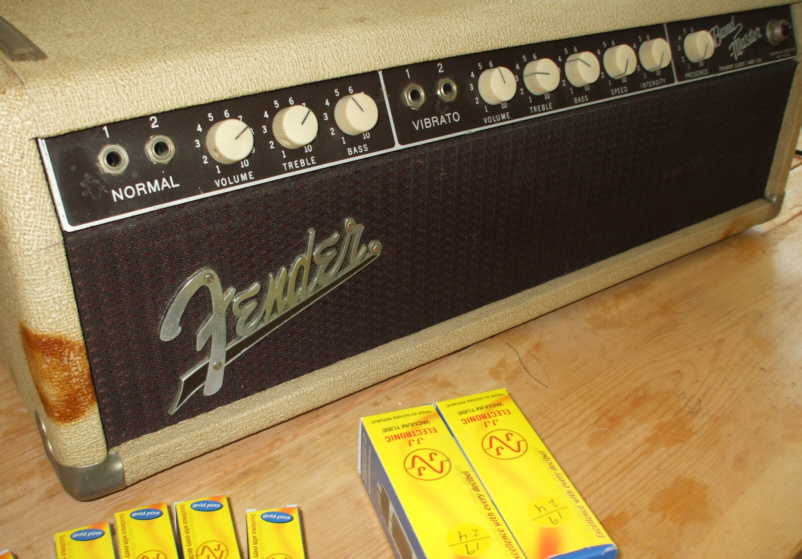
I opted for the JJ tubes for both pre and power amp. The 6L6's are a matched pair. This is very important because they work in a push pull combination. So the amp will operate to it best capacity with a matched set. The 12Ax7A, all six of them! are the pre amp and vibrato supply. These tubes feature gold plated pins, and are very quiet. There is no rectifier tube in this amp 6G7 A, and it has a grid bias. At a buck sixty the tubes dont come cheap, but do sound nice!
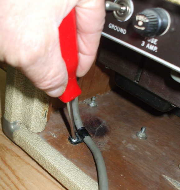
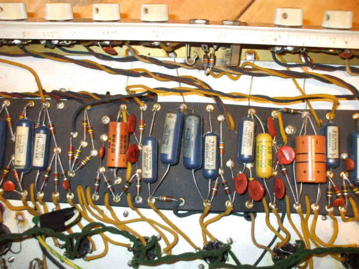
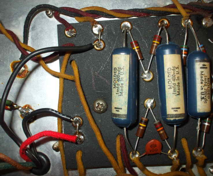
Ok, first I remove all the old tubes. Very carefully pulling them down, while wiggling them from side to side, and in a small circular motion. Tubes are very sensitive to shock and vibration, so go slow. I put them aside in my used bin. Next I unscrew the clip holding the power cord. Now before I say anymore, all amplifiers contain lethal voltage levels, which is stored in the filter caps. In older Fenders these are the brownish cardboard cans. Do not mess with them, if you do not have any experience with electronics. Filter caps can hold a charge for years if there are no bleeder resistors.
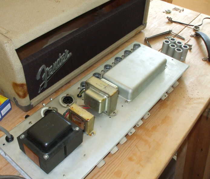
Next I remove the two chassis straps, and ease the chassis out. I'll work on that later. First I'll clean up the tolex, and face panel. Check out that nasty brown spot on the left. It's actualy a sap bleed out from a large Knot in the pine cabinet dirsctly beneath!
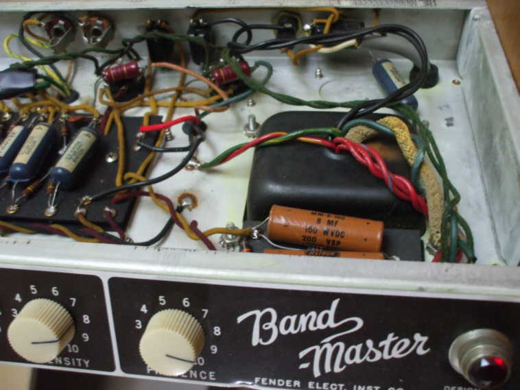
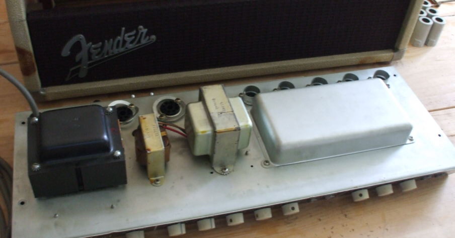
I check all of the transformers. There are two, the larger is the power transformer, the next big one is the output or audio transformer, and the small one is the choke. Are are marked EIA 606. thats good because that means Schumacher original parts. The big pan on the far side houses the filter caps. Lots of corrosion on the chassis.
Cool so far, KEEP GOING! Caps next? Then check for burned resistors, and other flaky things. And take pics, please. LOTS of pics.
No problem Will! Still a long way to go.
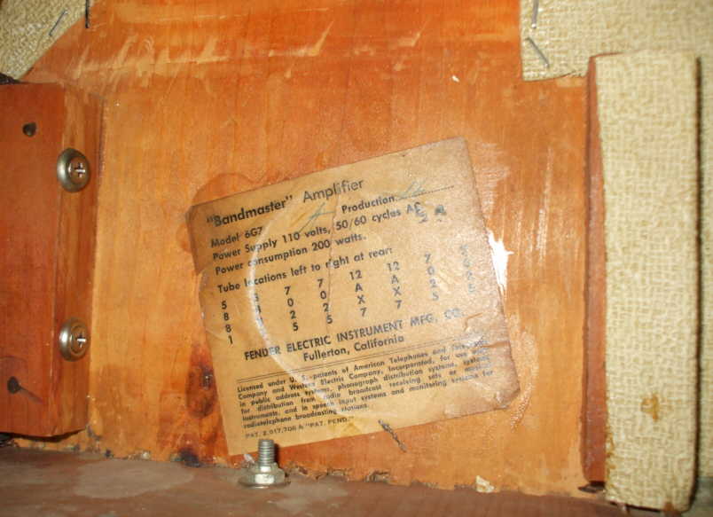
Now that the chassis is out I can have a good look inside the head cabinet. Here's a shot of the tube chart. While I'm inside looking around I want to get a good idea about the construction of the cabinet. I can see that the box is finger jointed pine. The cleats or strapping that the face baffle is fastened to is simply nailed and glued on. But the face baffle is screwed to it with finishing washers? While is certainly has lasted, I'm thinking I would rather glue and screw the cleats in place. It's a small thing, but I'de rather over build a cabinet than under build it. I guess they have to save money somewhere. The staple work is first rate, though
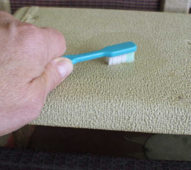
Ok, about the blond tolex. Nothing high tech about the clean up. It's in good shape with no tears, so I just used an old tooth brush with warm water and a bit of dish soap. It's water proof so no worries about it going through. Well it's water proof if it's in good condition! The head took about an hour to clean up. I avoided the seams on the corners where the vinyl was double cut. I dont want to soak and loosen the glue. After I scrub the surface for a bit to loosen the dirt, I wipe it away with a small piece of clean white tee shirt material. Not a fun job but necessary.
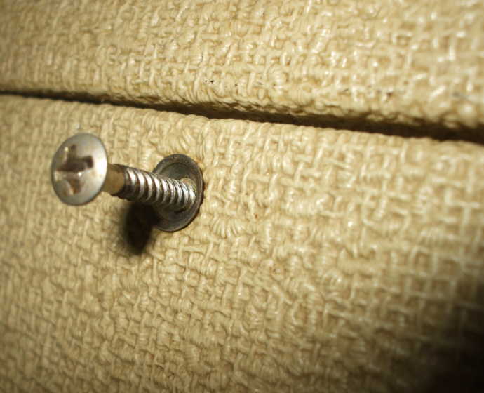
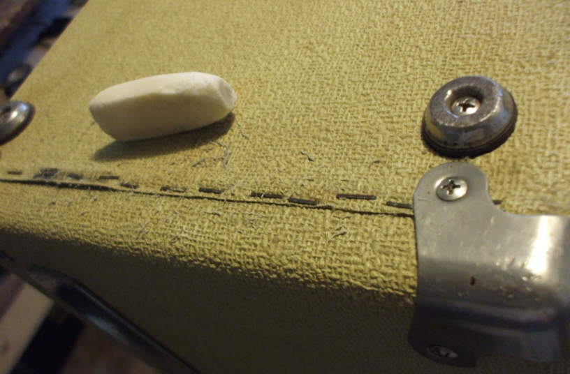
This shot gives you an idea of how deep the texture really is with the blond tolex covering material. Unfortunatly when I bought the amp the screws were all there, but the tea cup washers were not. After searching I located them st Speaneaur in Kitchener Ontario. In the US they can be found at Page auto supply, or for much more money The Amp Doctor in Germany has them too. I'de like to keep the amp as origonal as possible. A box of a hundred is only 4 bucks. I need 28 #8's for the back of the speaker cabinet, and 4 #6 for the heads back cover.
Any idea what the big orange stain is on the side? It looks remarkable circular, like if you could wrap a bottle bottom around that corner.
As to those cleats, I have always just glued and nail gunned them in. An 18 gauge brad or 5 works just fine while the glue is setting, and they are considerably cheaper than screws. Once the glue is cured, you're good to screw things into them with no problems. Titebond or poly glue works excellently.
I'm enjoying this topic, keep going. Can't wait to see it all done!
The orange stain is from sap bleeding trough from a large knot in the pine cabinet! There are a few of them. Gives it a bit of character
I'm big on the overkill, so any cabs I make will be all glue and screw, with finger jointed corners. Somehow nails just dont seem right in a cabinet, to me at least.
Okay, that makes sense. I've never seen that before, though. That's pretty serious, bleeding all the way through like that. I'll remember to get wood without knots for all my cabinets from now on. That is a challenge with pine, sometimes. Most times, in fact. Maybe I'll try poplar.
Oh, I forgot to mention that Fender used box joints on every cabinet of theirs I've ever seen. As far as I know, that is all they ever used. Once you build a jig to do them, they are really fairly easy and they hold like crazy. Plus, if you're making a jewelry box or something like that they look really nice.
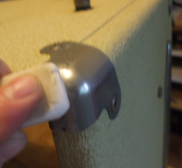
After at least two more hours with the tooth brush on the cabinet, I think I've got the tolex pretty clean. Now on to the chrome hardware and corners.
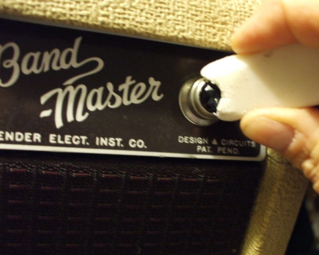
The best tool I found for that job was a white drafting eraser, 6 for a buck at the doller store. Dosen't scratch the metal or chrome. I don't want to use water on the hardware. After a bit of rubbing, the corners take on a soft natural shine.
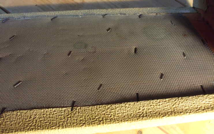
It's great for cleaning up rust of the staples on the bottem. I'm sure seeing a lot of staples in this amp.
Check out the skillfull manipulation of the staple gun on the back of the head panel!
That eraser didn't hold up to well to the course tolex, but it made a big difference on the cabinet hardware.
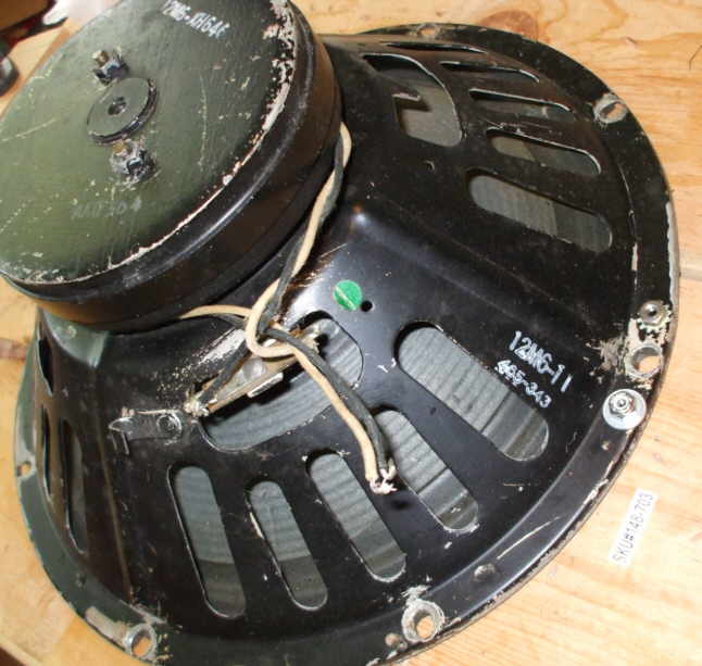
Time to open the speaker cabinet and get the speaker out. One found it's way into my challenger, years ago. So there's only one Oxford left to remove. I'll set it aside in case I decide to return the amp to origonal set up.
This speaker shows it's age. 465 is Oxfords code. the second three numbers tell the year and week of manufactor. At some point an aluminum dust cover was added. It still sounds good, but I opted for a set of Weber 125A's.
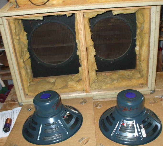
The Webers are like a reproduction of the origonal Jensen Blue bells. They have a very thin cone, and alnico magnets which really shape the sound. Strong clear highs, they stay clean longer than the ceramic magnet Oxfords.
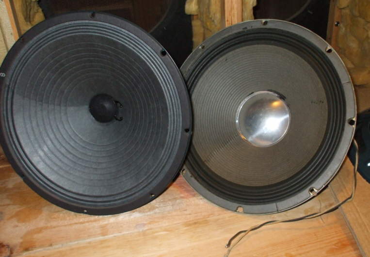
Heres a side by side comparison of the Weber and the origonal Oxford.
The voice coil is very small.
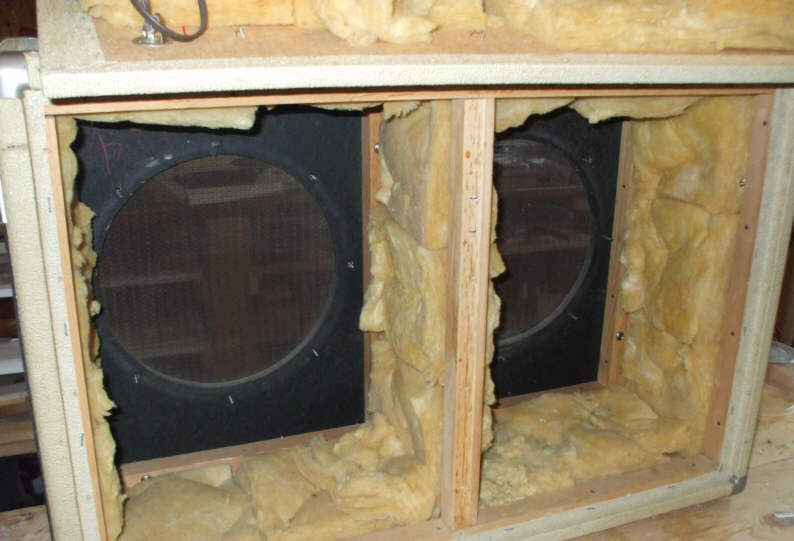
Next I remove the center baffle.
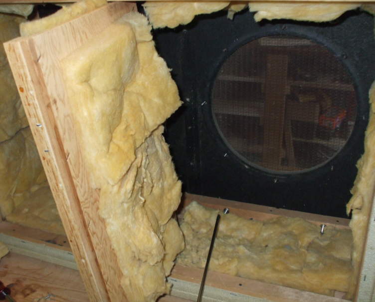
Now I can get that nasty insulation out of there. I use my fret bending plyers.

I don't know that I would be going through nearly as much trouble as you are. For instance, I'd be leaving the old insulation in the cabinet, and just swap out the speakers. Unless, of course, you've got some other approach to the damping. But hey, it's your amp, do whatever you want with it. I'm just a bit lazier, I guess.
Great series going, I can't wait to see the final product. I hope you're planning on some sound files when it's completed!
Pulling that insulation was no trouble, now the guitar I built to go with the amp, that's another story
I bet that thick tolex covering goes a long way to keeping this cabinet from getting too boomy. Any way I saved the insulation and even the original staples and boxed it up. I am planning on using this cab so I want it stage ready.
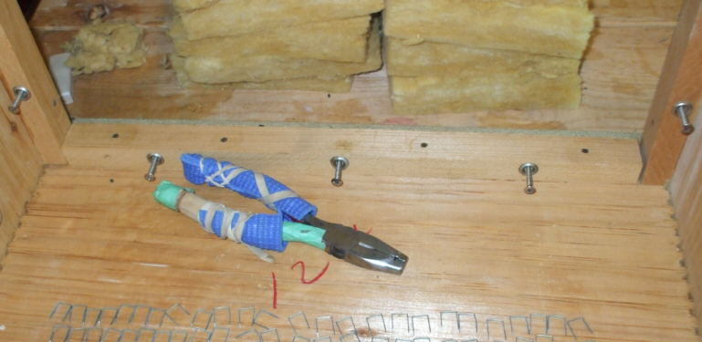
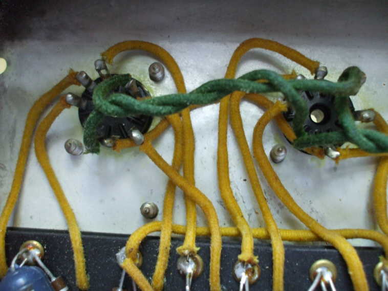
Besides, take a look at the corrosion on these fittings!! Looks kind of like nuclear fur, what is that? Probibly caused by being buried under all that insulation. It was so powdery, it's starting to deteriorate. Those giant knots from the inside are causing that sap bleed out beneith the tolex. I cleaned them up with a small t shirt swatch and WD-40, being carefull to stay off the pine. I didn't want to stain it.
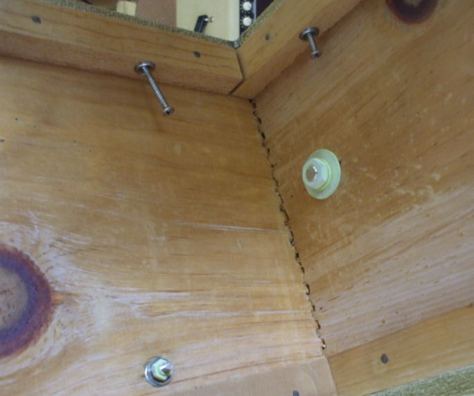
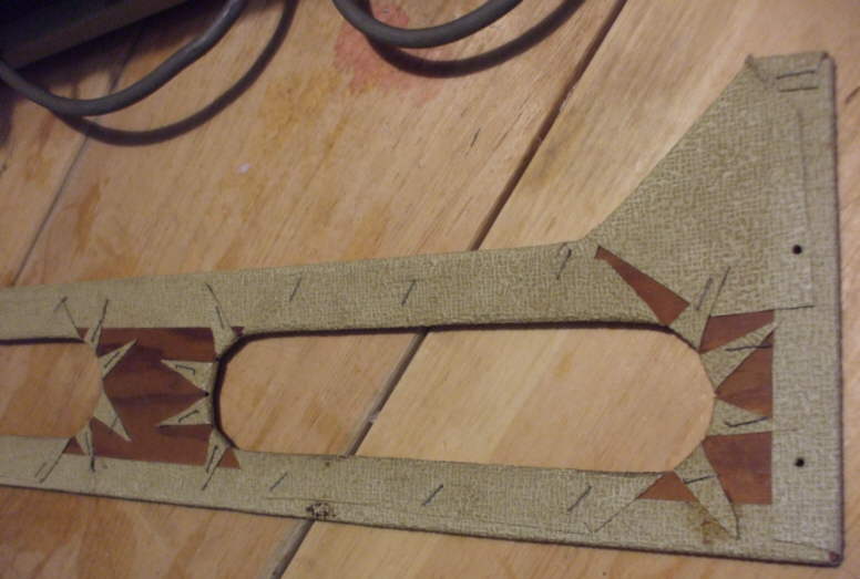
Here's a close up. There's a similar green fuzz inside the chassis as well around the tube sockets. You can see the finger joint corner from the inside. Lots of tear our. No doubt this could be avoided with a disposible backer when the joints are cut.
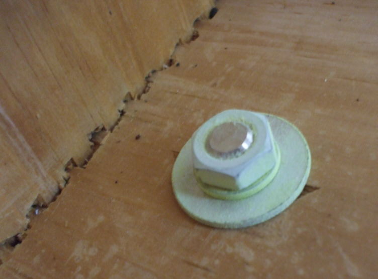
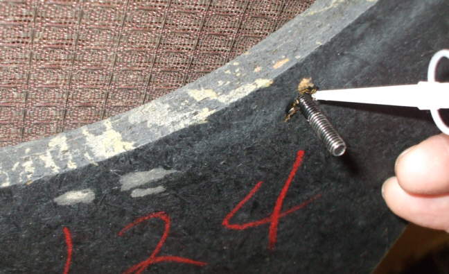
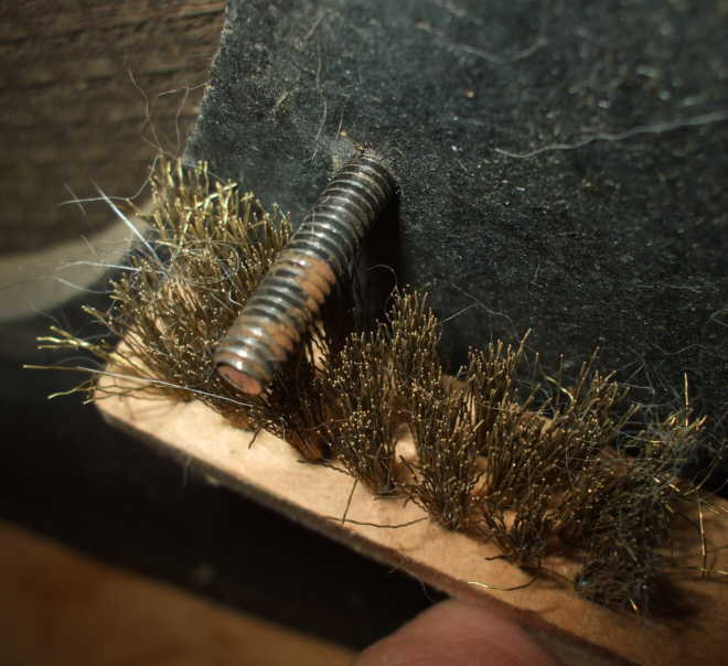
Next it's the speaker baffle. MDF, or particle board back in the day, which for the first time around 1963 made it's debut on the production line. Lucky me. That could explain why some of the mounting studs have become loose, and are pushing out. Particle board is not great at holding screws in heavy vibration mode. The solid ones measure out to 3/4", so thats where I'll back in and super glue the others. Hopefully they'll hold or I'll have to make a new baffle from plywood.
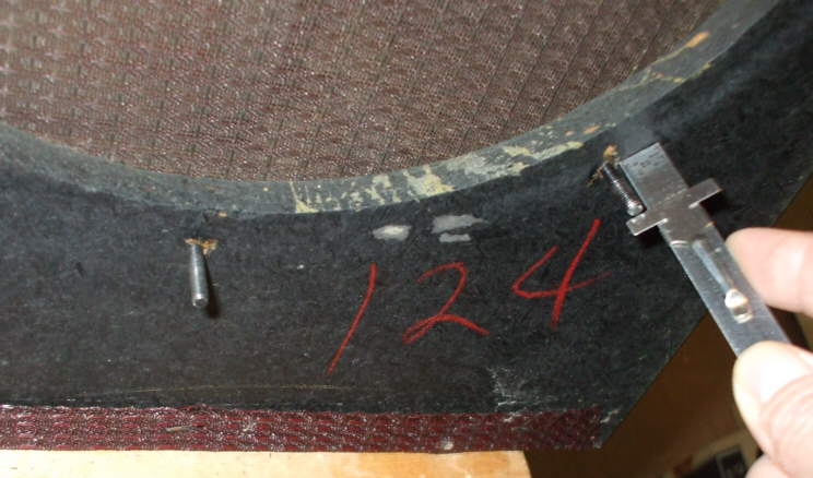
The red 124 is marked on all the cabinet parts. I read that the assembler would go down line and match up parts that fit best.
CA until it stops turning.
Oh, first I removed the rust...
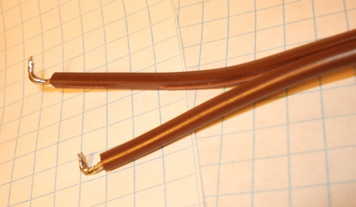
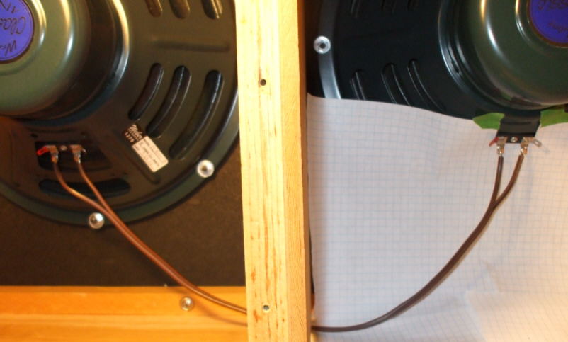
Now that the speakers are all snuged down, I can wire them up. I'm using a parallel hook up as is stock for this cabinet. Just like the original, I'm using 16 gauge lamp cord.
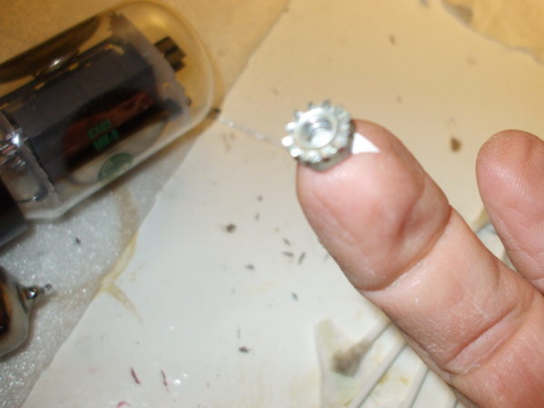
The Baffle is very important. It needs to be dead flat so the speakers mount with a minimum of rattling, and vibration. They will sound weak if they're not mounted properly. Hardwood ply would be a nice upgrade. Tee nuts would also be a better mechanical connector than the threaded studs in there now.

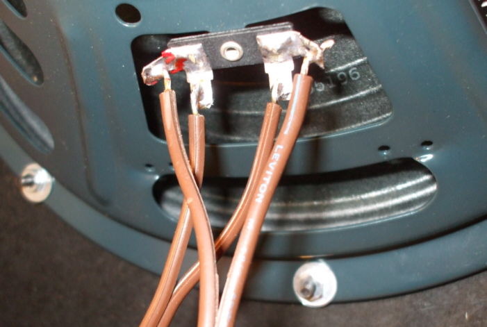
I prep the leads with a hook shape, and tin them with solder.
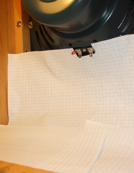
A quick paper screen so I dont drip any solder onto the back of that cone.
Next are the leads to the input jack.
I used a couple of spring clamps as helpers to solder up the replacement jack. The origonal lead was cracked so I opted for a new one.
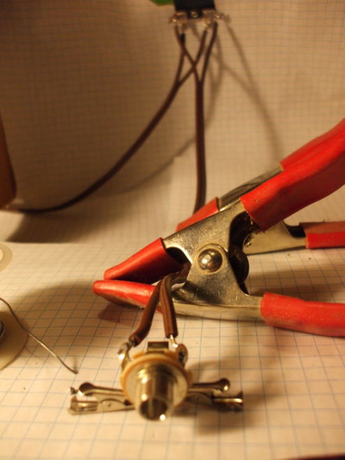
The pair of switchcraft jacks, old and new. Not much difference after all these years. I'll box the old one just in case.

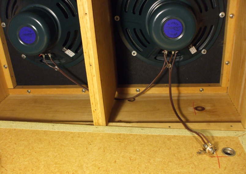
The finished parallel hook up. Only the chassis' left to clean up now!
Finaly I can get at the chassis.
I was surprised at the amount of corrosion, since the amp wasn't used much of late.
Here's the pre amp tube sockets.
Your tutorial rocks mightily, Andy. I love those old Bandmasters, getting one with a honkin' big 15 inch closed back speaker cabinet in it changed the way I play for the better.
Thanks Ellie! Yeah Bandmasters have a BIG sound, and with a speaker set up that suits your playing style, like walking on air. I like the close back cabinet as well. I think it drives the speaker harder, than an open back.
CCR's big open rythem guitar are pure Bandmaster, and how about Scotty Moore of Elvis.
High Voltage can be present in the chassis! Dont attempt this unless you are completely sure of what you are doing!
Before I get into the actual cleaning, I check for any residual voltage at the filter caps. I have left the amp standing unplugged for two weeks to allow the bleeder resistors to do their thing. No voltage was present so I'm good to go. Had there been any it can be discharged with a jumper made of a, 470 ohm, 1 watt resistor soldered to two insulated alligator clips.
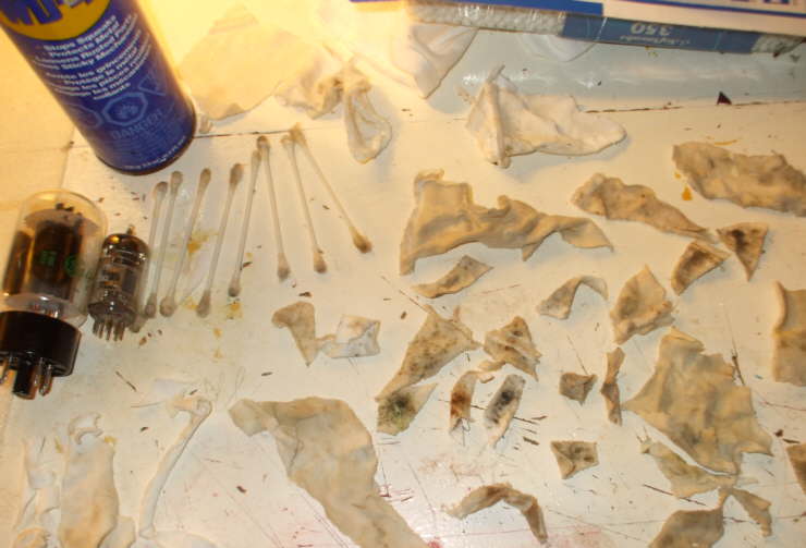
I only work with one hand through the entire cleaning process so as to avoid making myself the human circuit! I even wear an old work glove on my left hand to remind me to not use it. I use WD-40, 8 0r ten Q-tips, and about an 8" x 8" square of clean white T shirt cut into small squares. Another super handy tool I improvised was a bamboo skewer stick. I spray a bit of WD on a cloth swatch and with the help of the stick I can move it about the chassis, even beneith wires.
Good and filthy, it took about an hour and a half to go through it.
The tubes are dead ones I use to insert and clean up the sockets. The cleaner the sockets, the cleaner and louder the amp.
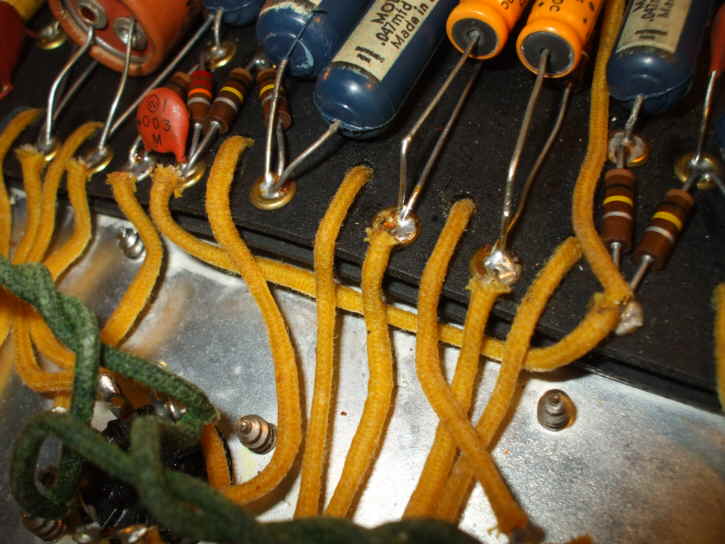
Getting under and around everything took some patience. The Q tip was for the component leads and the contact points, each solder joint is cleaned and checked for cracks.

Tube sockets are real clean now.
It's hard to imagine how all that cool tone comes from all this, but it does. You can see a heat stress warp in the board here, still everything works.

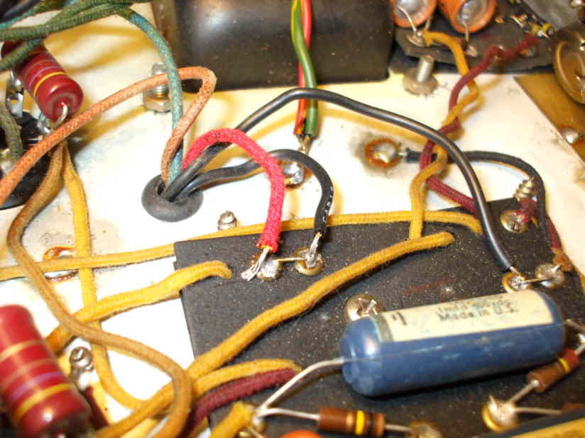
While I was probeing and cleaning I found one solder joint that didn't look right. It's the bright red wire comeing off the output transformer, which is linked to the standby switch.

That joint is not properly soldered, and had it come loose while the amp was live it would have left the standby switch ungrounded, giving me a nasty shock!
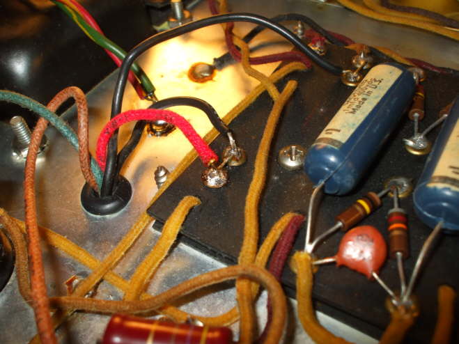
Now it's properly soldered. The eyelets are 3/16" and take a lot of solder to make a solid connection.
Is that a solder bridge between the red wire and the black wire next to it?
I hate to ask, as it seems you know what you're doing. Still it looks suspicious to me.
It's a jumper. You can see it and another in post #54. I have to agree, though, it is bad practice to intentionally wire a red and black lead to the same connection, but that may not have been common practice when this amp was built.
I read that the eyelet boards were sub contracted out, and the workers were on piece work so speedy production was 'of the essence'
Here's a better pic of the board and those two jumpers and conection to ground. The board shows a small crack below the screw, and the letter K in red?
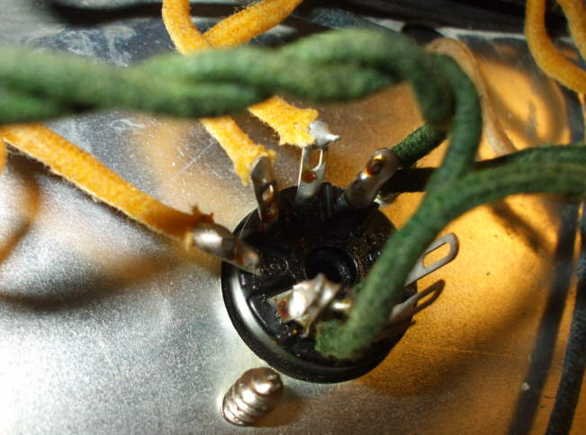
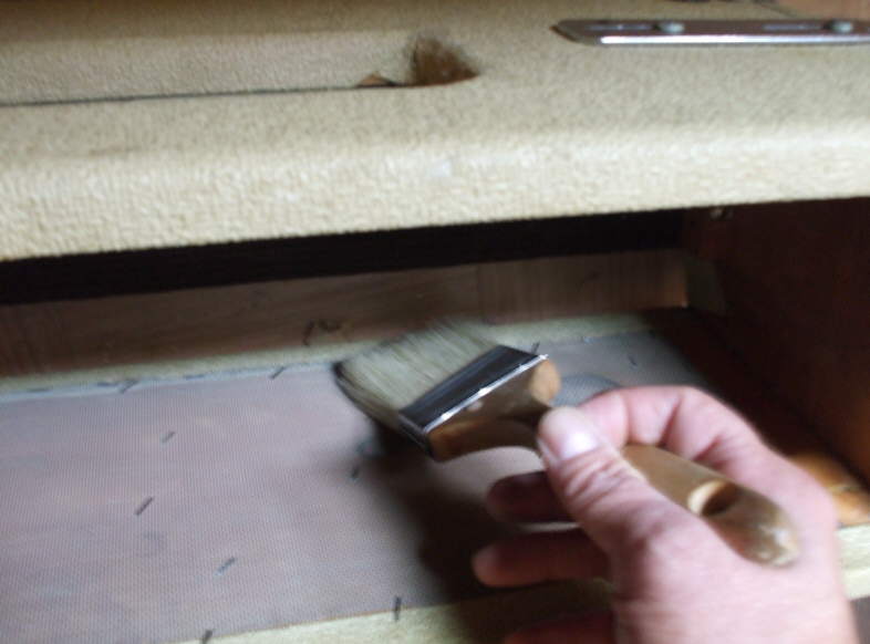
OK, back to the mission. The screen which grounds out via contact with the open top of the chassis needs a little attention.
The forward edge is getting a little frayed, so I pass a dust brush across it to show the loose wire. I trim the edge clean so no small bits of screen can fall into the amp, and potentialy cause a short.
I found a few small pieces when I did the clean out.
Now the chassis is ready to go back into the cabinet. I use a small chunk of pink foam insulation to help support the weight of the amp while I attach the straps and screws. Well I was able to get three screws back in OK, but that last one back..actualy it's up front behind the power transformer..what a pain. I must have tried 30 times to hold that nut and reach way back there. I just couldn't do it.
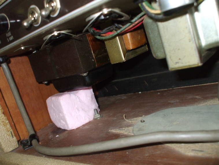
The next day I got an idea. There's really only room for one finger back there so I use a little double stick carpet tape and I got it on the first try!
Oh, but you're not ready to button that bad boy up, yet! You still have the filter caps to check out, and those are the most likely to be shot. You're doing a great job, but take care of the rest of what needs to be done while you're in there. You'll be glad you did...
Will, I'm curious what makes you think Andreas doesn't know what he's doing?
Hal, I would never make so insulting a suggestion. But if one is opening up an old (and it being a blond, it's clearly old) amp without taking care of the electrical parts that will no doubt be worn out, then one is only doing half (if not less than) the job.
I'm not trying to be insulting at all. It just seems to me that if one is going to go to all that trouble, then do the job right. That involves replacing the electrolytics, checking for worn out and burned resistors (especially the plate resistors, in a Fender), cleaning up all the tube sockets, checking voltages, bias, etc.
And I thought the point of the forum was to be helpful to others. If I were doing this kind of thing, I would want help from those who had done this kind of thing before. Sorry for trying to be helpful. I will refrain from it in the future.
Boys, please play nicely.
I play tested the amp befor the tune up and found it has good volume on all channels, and very clean so I dont see any need to replace the filter caps. They seem to be working fine. When they start to crackle and hiss I'll have a go at them, but for now they're staying put. Thanks for the heads up Will, your suggestions are always welcome. So when I do have to replace the caps, as they are nearing the end of their lives, I will post the procedure.
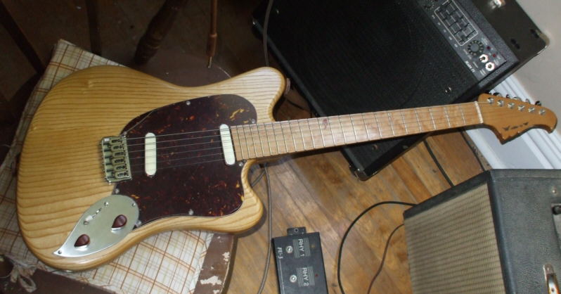
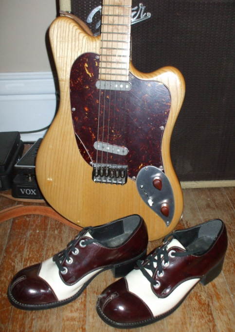
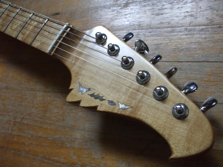
Meanwhile, here a look at my latest Blonde Alnico 2 pickup guitar I built to accompany my Bandmaster. I was going for Strawberry Blonde look to match the amp.
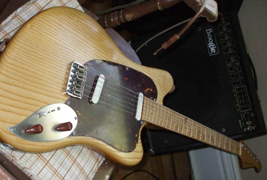
The three ply dark tortoise pick guard goes with the Oxblood grill cloth, and the striped grain on that hard white ash body compliments the Blonde tolex of the amp covering material for a natural Blonde on Blonde look. Alnico 2 magnets in flat top bobbins with Aluminum pick up caps, match with the Aluminum cover plate. A pair of pine root pointer knobs trim out the guitar. I left the pickups unpotted, and they are very sassy and, well... just plain mouthy. Needless to say the all maple neck, which is fashioned from quarter sawn birds eye maple with a birds eye maple fingerboard, contributes to an overall brightness of tone.
Hey Andreas, way back in post 3 you said:
>"There is no rectifier tube in this amp 6G7 A, as it has a fixed bias"
I'm guessing it must be a typo, but I can't figure out for the life of me what you mean.
Did you mean to say it has diode rectification and it's also fixed bias?
Greg: You're right on that one, I missed that statement back then. Bias and the rectifier have nothing to do with each other. One smooths out the AC into DC, the other sets the operating range of the tubes. Two totally different things.
Plus, this is NOT a fixed bias amp. It is an adjustable bias, but it's not set up for EASY bias changes. To do so requires changing the value of the bias resistor, which is not an easy fix. Fender really SHOULD have done an adjustable pot on this for this setting. It would have saved hundreds of hours or repair time.
Good catch.
I'm no expert on amp jargon, but doesn't "fixed bias" refer to mode of operation, as opposed to a cathode follower? Is it the AA270 (edit) circuit?
The amp I built has an adjustable fixed bias, which is what Will is talking about. It stll sounds like an oximoron to me, adjustable fixed bias.
The terminology should be "grid bias" vs. "cathode bias." Grid bias delivers a negative voltage to the grid, which can be adjusted or not, depending on the circuit design, as Will says. That's fixed bias, despite the adjustability.
Cathode bias uses a resistor between the cathode and ground. The voltage drop across the resistor creates a positive voltage on the cathode, which performs the same function as the negative voltage on the grid: It sets the "idle speed" of the tube--the number of watts it dissipates while there's no signal. Cathode bias is technically adjustable bias because it's self-adjusting: If the tube draws more current, the voltage drop across the cathode resistor increases, raising the positive voltage on the grid, limiting the flow of electrons, so the tube doesn't go into runaway. To change the basic operating level, you have to take out a big power resistor and replace it with another.
So grid bias is fixed bias, even though it may be adjustable.
Cathode bias is (self) adjustable, even though it's fixed by a nonadjustable resistor.
Clear?
Oh, and cathode follower is something else altogether, not relevant to power tube bias.
Greg, you are correct. I have fixed the typo. It now reads, 'and' has a grid bias. Thanks for clearing that up Will.
No doubt Fender was once again trying to save money by not including a pot allowing for bias adjustment.
Rodger it's the 6G7 A version.
Thanks Bill for the info on biasing.
If you look at it on a pair of schematics, say a Fender Pro 5E5 model, and this particular Bandmaster, the 6G7A, it's easy to see the difference between the two. Locate the power amp tubes, and then look at the center left (9:00 area) part of those on the schematic. You can see the lines we are talking about, and if you see where they are going in each case, you will see that there is a lot ore circuitry around the later Bandmaster. That is the "adjustable" bias, even though it's annoying to do. It involves a separate winding from the transformer, a diode, at least two resistors and at least one cap, if not more. All this sets a negative voltage to set the running point of the tubes. This is what we think of as the classic Fender clean sound.
In the Pro, the same lines go to a resistor and a cap, which go to ground. This is also how the Deluxe and other earlier (tweed) amps were set up, though the later ones started doing the adjustable. This type of bias tends to break up earlier, resulting in a softer volume level, but with a lot of guts and fatness to the tone. Add that to the tone stack setup in these amps, and you've got a fat monster. This is more what we think of as the early Fender sound. I tend to like this, though I like the other, too.
In fact, I built an amp that has a switch so that you can switch between the two bias options whenever you want. My next one will include that little option as well. It's very useful in a recording amp as well as a gigging amp.
Here's a schematic of the 6G7A.
Love to see that amp Will.
Thanks, Bill. That's much clearer to me than anything I've read, I'm a beginner with tube circuits. I've built a P1eXterme, but haven't really had time to tinker with it much. I've got several power tubes I haven't tried, and I'd also like to get a more sensitive speaker than the Celestion Rocket 30 that's in it now.
Andreas, I like the guitar. It's nice to see you do simple elegance as well as ornate sculpture.
I meant to say how much I like that guitar. It's elegant. Nice retro touches.
I didn't realize that it was a 6G7A at first. That tremolo circuit is insane! 2-triode low-frequency oscillator, a phase splitter, and push-pull output driving the signal. Way too complicated (three tubes), but a sound all its own. Very cool.
When it finally needs new caps, good luck finding 600V caps. You'd probably have to go with stacked 47uF 400/450V caps and balance resistors. I saw an article by R. G. Keen a while back that advocated using plastic film capacitors (used in switching power supplies and as motor run caps) instead of electrolytics. They're available in high voltages and don't have any chemistry issues over time.
Just found a link to the article:
http://www.premierguitar.com/Magazine/Issue/2008/Oct/The_Immortal_Amp_Mods_Pt_4.aspx
I knew there was a reason I was avoiding changing those filter caps!
Thanks Bill, that information will come in very handy when it's time.
Hopefully later than sooner. I'm looking for caps now, so I have them ready.
Do you expect there would be any significant change in the sound between plastic film caps versus paper?
Another vote for the general bitchin'ness of the guitar. Love the simplicity and '60s vibe.
Where did you get the 3-ply tortoise?
As for all that electronics talk.....huh?
Any time you replace old caps with new, you hear different things from the amp. I'm sure your existing caps have drifted and the ESR is probably high. So fresh caps would firm up the bass and probably reduce harmonic distortion--cleaner cleans. Plastic film caps have low ESR, which makes them preferable to stacking lower-voltage electrolytics. Stacking adds the internal resistance of each cap.
As for all that electronics talk.....huh?
Yeah, me too!
Thanks for the kudos on the guitar!
Mike that 3 ply came from Allparts, it's the darker of the two they have. It's only tortoise on top with white/Black/white in between.
I learned a really cool lesson in Guitar building economics with that build...1 fully inlayed custom guitar equals 4 un-inlayed custom guitars, in terms of time commitment.
As I've said before Amps are a huge part of a guitars voice,
and the more I can learn about them the better I can play with the overall sound. So much to learn, so little time.
Bill, I'm wondering if there is enough room on the filter board to house a stacked set of caps, or will I need to leave the pan cover off?
The filter caps are housed in that large pan on the far right of the chassis.
I take it you decided not to go the plastic film cap route?
I wouldn't leave the pan cover off. Modern 450V 47uF caps are pretty small. You can probably fit them in two half-overlapped layers.
F&T is a good choice, and 220K is a fairly standard balance resistor value. If you want low-ESR 105°C caps, David Allen has GSC caps on his parts page at allenamps.com. His supplier just ran out of them (I tried to buy a couple hundred), so get them sooner rather than later.
Actualy I'm leaning towards the Allesandro 630V 47uF caps.
Alessandro has electrolytics? I thought they just did coupling and tone capacitors. I didn't see any electrolytics on their site. I did see a .047uF 630V coupling cap, though.
I did notice, however, that Antique Electronics (www.tubesandmore.com) has 600V 20uF Sprague Atoms. Atoms are big and functionally obsolete. In fact, many Atoms are just an aluminum tube with a smaller, modern capacitor inside. I don't know about the 600V version; never used it.
Nice guitar, Andy. You going to get shoes to match the amp and guitar Combo?
I did with my leopoard Dano copy, my leopard Bandmaster clone and my leopard painted Chuck Taylors.
Thanks for the heads up on the caps Bill, F&T it is.
You going to get shoes to match the amp and guitar Combo?
Nope, already got'em!
...Cant get no tone, if aint got no Shoes
And with an oxblood grille cloth, too! I LOVE it. Do you wear a seersucker suit with those shoes while you play? That seems appropriate, for some reason. Or just a white one. Love it. No one else in the band will look nearly as classy. The amp is in good company.
Actually I wore a 70's lime green polyester leisure suit the last time I gigged with those shoes. Kind of like a disco blues review
Your right Will, white would have looked better.
Oh, man, that pic puts a smile on my face!
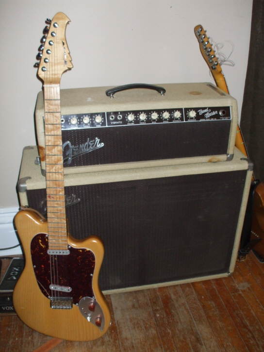
Hey cool! Here's a pic of the happy couple.
The headstock is oversized like the 70's Fenders.
Black pearl inlay. The 510 mini gotoh tuners are nice and light, and the buttons feal nicer than the bulky Schallers I usually use.
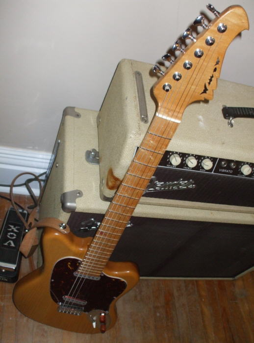
The honeymoon shot
I left the neck clean with only a small pipestone inlay at the 12th fret, in a lightly figured flat sawn birds eye maple board, 12" rasius.
That quarter cut of the neck stock really throws the light.
How do you get away without string trees?
By starting out with a neck blank that a full inch thick, I route off 3/8"- 1/2" for the headstock face. This lowers the tuners slightly. Then I use a fingerboard that finishes out at a full quarter inch at the shoulder, this raises the string plane higher. The two changes combined allow me to gain a degree or two, just enough break angle to avoid a string tree. I like to bend a lot of notes on the high strings, and string trees tend to hang up.
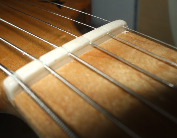
Here a close up from when I cut the nut slot, it kind of shows the break angle on the high E string.
I mark the pencil line with a split pencil( sanded half flat ) off the finished fret tops. That gives me a 'no go' past line when I cut the slot depth.
Are those flatwounds?
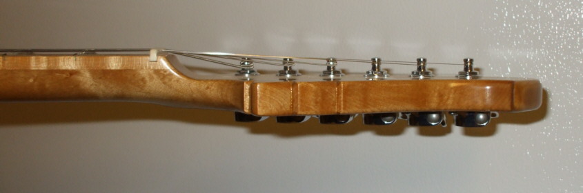
Wondering if you could post a sideways picture of the headstock and neck transition. I'm only recently starting to build necks with the drop down headstock, and have one that I rejected because the headstock face is lower than usual. I started out with a 1" blank and took the headstock down to almost final thickness (removing material from the face) and carved out my truss slot, just kind of flying blind. And now I'm concerned the headstock might drop too far and have a weak spot. Any opinions on how low is too low?
They're Roundwound 56-12.
Matthew I'll get you a side profil shot tonight. As long as your headstock finishes out at 1/2" thick, you will be fine. No need to worry, maple is incredibly strong and stiff.
Here's a side profile that shows the break angle. You can also see the quarter sawn birds eye figure.
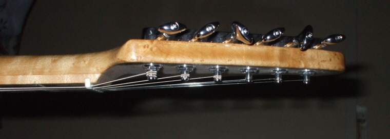
This one is shows it better.
Looks like it needs a string T to me. Also need to trim the nut down to the top of the strings.
Thanks for the pics, Andreas. I'm just concerned that the plane of my headstock face and the plane of the back of the neck are only about 1/4" apart, and I thought it might get excessively weak there. But it doesn't seem to flex any more than the factory necks I have. Actually less, I think, because I use quartersawn wood instead of flat. Sorry to hijack your thread, but thanks for your help! That is a lovely guitar and that amp refab is amazing. I can barely understand some of it, but I still tried to absorb everything that was going on. Love your work!
Glad your getting something out of this, Matthew!
Barry, I dug out my angle gage and measured my strat with a roller tree in place. The high E strings break angle measures out at 9-10 degrees. The high E on the Blonde comes in at 5 degrees, with no tree. To double check I put the guitar to the true acid test. I played it accousticly in a quiet room. No amp to colour things. It rings, stings, honks and bends like a dream! and even better returns back to pitch. A little dry soap in the slot helps with that too. So, yeah it does work well, for me at least, going treeless.
I find the guitar now has a more balanced tension across all the strings, as well as a balanced volume across all strings.
The 1/2" drop from the fingerboard top to the headstock face shows.
When I inlay maple, I overtape the area with green painters tape befor proceeding. First I should say I have sanded the face to #600 grit and have applied 2 coats of my choosen finish, Danish oil. The tape keeps knife wounds to the surface to a minimum. I try to spend a lot of time on the perimiter cuts so the outline will be as clean as possible. Miscuts in maple are brutally revealing, and virtualy impossible to hide with fill, etc. So I take my time, and wear the magnifier. Get the jazz station on softly in the back ground, too.
My goal is to get the inlay into the cavity so that it's top surface is just proud of the headstock face. I then go to a well sharpened and edge burnished curved cabinet scraper to bring it level. The tape is still in place. The last step is to 400-600 grit sand the tape away. CA glue should cure after 3-4 days enough to reapply the finish. It's very tedious work, but I like the end result. Notice the face grain has the typical flecks of a quarter sawn cut. This neck came out very stiff.

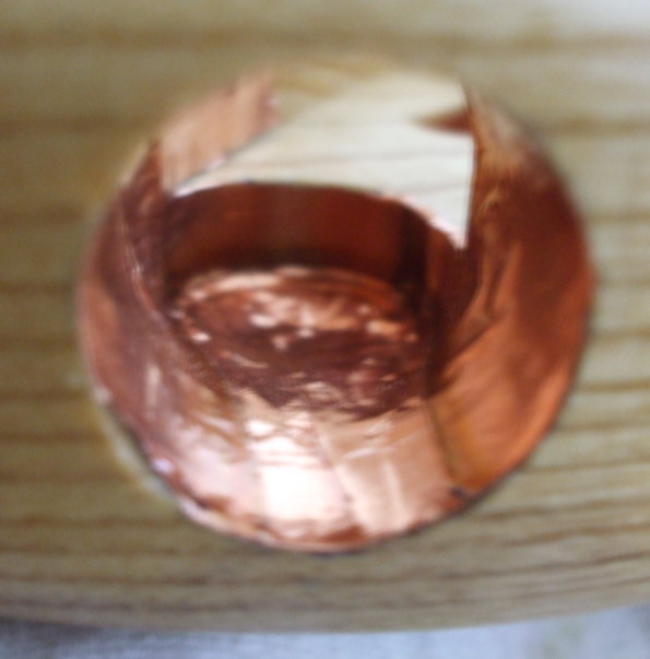
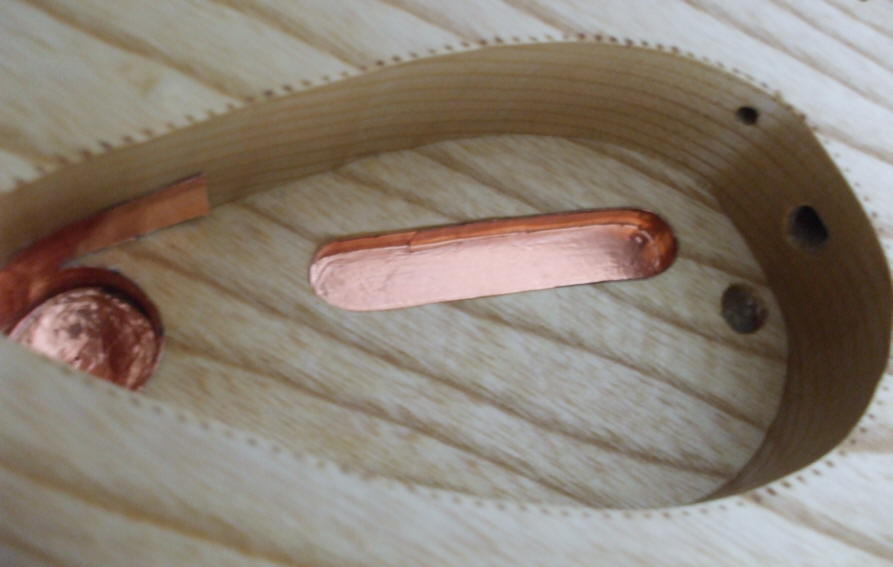
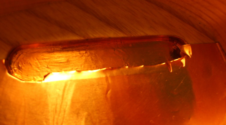
OK, back to the electronic part of the program, check out this lovely opening for the electro socket. All copper clad. Before I line the cavities with shielding foil, I sand them smooth, and then seal them with a few coats of clear lacquer applied with a small brush. The reason I seal the cavity is to ensure good adhesion. Dry unsealed end grain will likely absorb the foils adhesive, quickly and cause it to fall off sooner.
A bit like sizeing before wallpaper. The foil has a pretty good tack, and can be repositioned with the sealer coats.
I like to start with the hard parts, first.
Next I line the switch recess. You can see that all the conduits are pre drilled, including the ever important string ground.
This is turning into an amazing tutorial!
Thanks, Andreas.
One good thing about this tutorial is that it shows your close attention to the details, Andreas. All those details really add up!
Thanks guys! Yeah I'm a freak for the little things, might be a hold over from when I was a kid and built a lot of plastic tank and airplane models, plus I'm near sighted so it comes naturaly
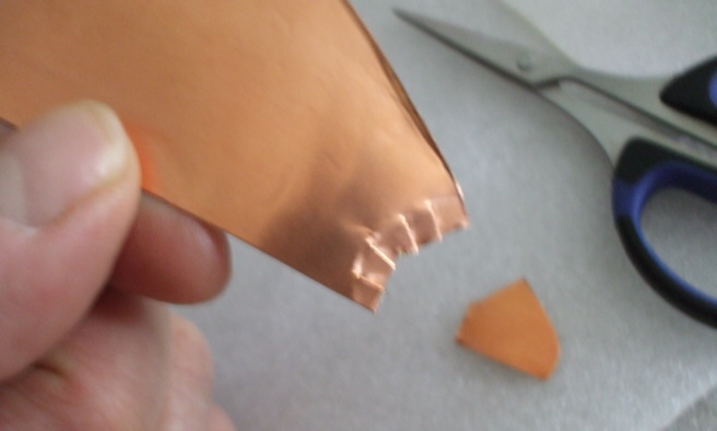
Now I can lay in the large 'easy' pieces for the cavity floor. I cut a piece larger than needed then hold it over the cavity and take an impression. From that I can cut out the shape leaving it just slightly larger than needed. I crimp up the edge with my thumb nail. This is important because it ensures a complete shield. Remember that the adhesive is actually conductive.
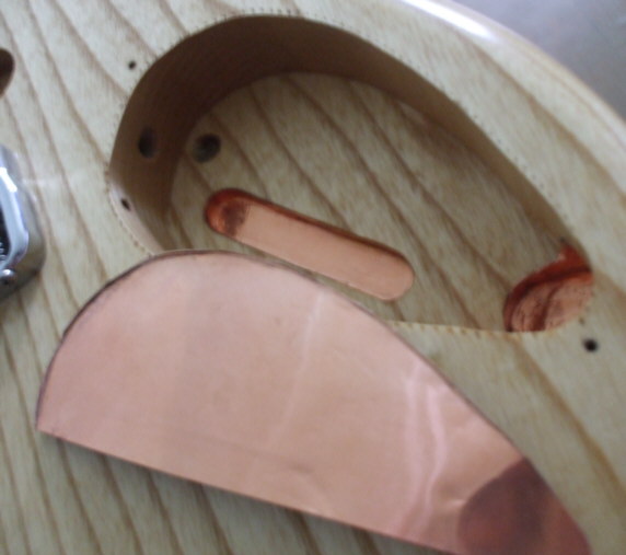
Next I remove the excess over the jack section, and make a few relief cuts, like so...
Now it can go in. You'll be happy if you sealed the cavity now because you can reposition as much as needed to get it just right. Notice no kinks. Love that sealer! The edge overlap is just enough.
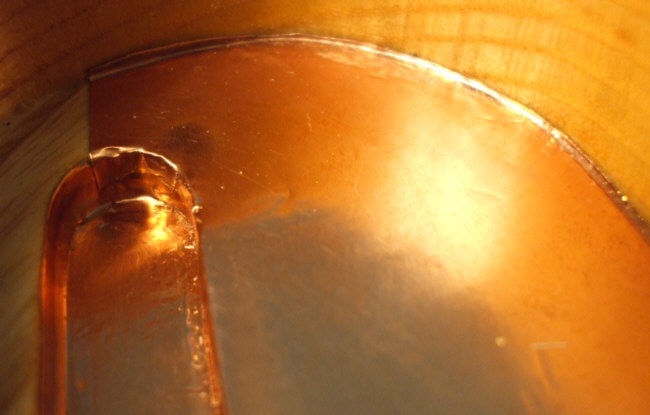
I used the same bamboo BBQ skewer stick that I probed the Amplifiers chassis here to burnish down the overlap, and tighten up things in the corners. One of my more unusual guitar building tools!
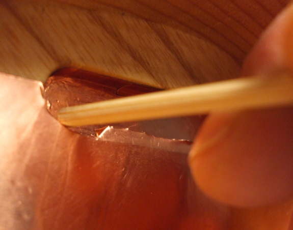
Try not to work the foil if your hands are dirty or you've just eaten a bag of chips. It will tarnish quickly. I wear a white glove like the buck store sells to rub it all down and keep it clean.
Here's the cavity floor all finished up..
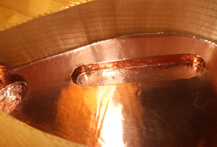
The sides are done with the smaller roll of foil. A nice feature about the foil is you can imprint it with a dead ball point pen.
I lay the piece of a writing pad, before you remove the backing, and sign what you want. I put my brand name, date, and where I built it.
Now this cavity is ready for electronic components and hook up!

Dang, you make it just as pretty on the inside! It's a shame it must be covered up to keep the RF out.
I hear you Nick, Thanks. When I first started building I must admit I was very intimidated by the electronic part of the guitar. I would treat that part of the job as a necessary evil. Well it didn't take me long to realise that it's simply much to important to rush or do a half ass job and, just get by. If the sum of an electric guitar is it's parts and how they all go together...
Now I'm a sponge for all things electrical, spare no detail and with the help of smart folks here at the MIMForum like Mark, Will and Bill, learning is fun.
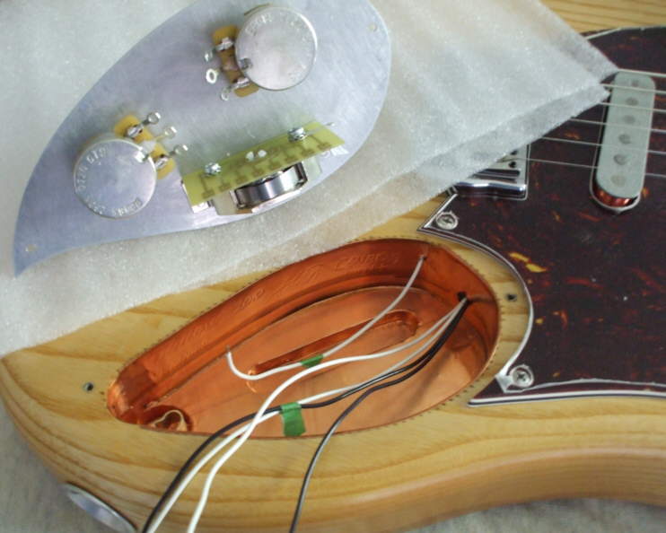
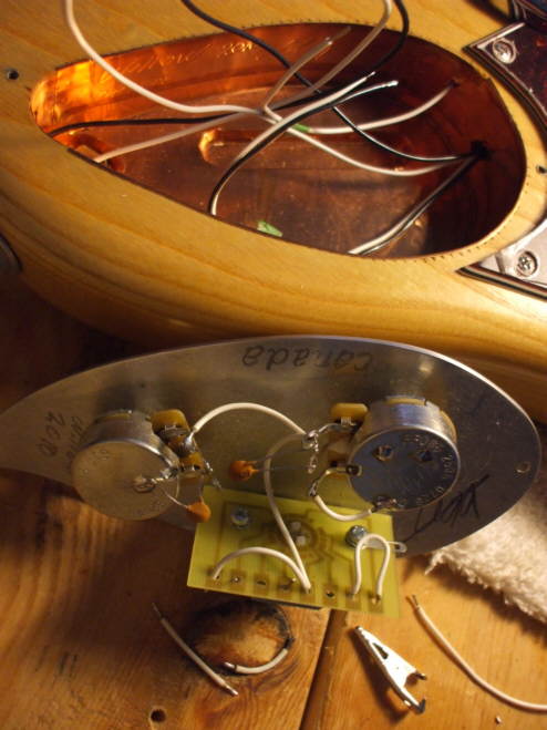
The components are all in. I used a pair of CTS 250k pots for the volume and tone, as well as the schaller super switch. I like this switch because it is heavy duty built, not like some other standard 3 ways. It has an actual circuit board for the contacts.The plate to which the components are mounted is hand fabricated from 1/8" aluminum. The output jack is a 1/4" switchcraft into an electrosocket, again far superior to a standars tele style jack out.
One thing with need to watch for when you've sheilded a cavity is that the out put jack dosent ground out on the foil when the guitar is pluged in. Make sure there is enough clearence.
Now I can make the conections.
Beautiful work. I will have to use some of your techniques when I finish up the inside of my latest one coming up. Thanks for the tutorial.
No problem bud.
Now with the hook up. First I clean all the surfaces and contact points to be soldered with Naphtha. Clean means solid long lasting connections. Then I start with the jumpers on the switch, and the tone capacitors. They are .001's. The one across the two volume legs helps keep the treble 'there' when I roll the volume down. This really helps the guitar sound acoustic at lower volume levels. Rythem playing! I choose another .001 on the tone pot too. Not much of a treble reduction so the tone is real hot and nasty.
I try to locate the jumpers and all wires in a sensible way, instead of just jamming everything in there! I tack the connections first, then when they're all in I solder them. The toughest part of soldering is keeping your irons tip clean. I use a sponge in a bowl of water to wipe the tip.
Nice, clean control cavity shielding there. Wow! A blonde Bandmaster was my first real amp too.
A blonde Bandmaster was my first real amp too.
I just finished reading Keith's book, Life, and he says how much he wanted to sound like Scotty Moore, who played a Bandmaster. So the Bandmaster sound inspired some great classics!!
We're in good company Jonathan.
Great tips on soldering: clif kachinske, "Soldering gun and techniques" #20, 05:59pm Jan 7, 2011 EST
Andreas, I don't think that a .001 cap for tone will do much of anything at all! That's a far cry from the .02 that is standard, and it doesn't matter what cap you use if your tone control is all the way down. You're just not going to get much action at all from a .001 cap.
You're just not going to get much action at all from a .001 cap.
That's exactly what I like about it! It leaves me with a nice smokey sound, almost clean, but not. More dry and edgy than smooth, if that makes sense.
Next step, I braid up my output wires, one ground and 'hot' on the center leg of the volume, and finaly the pickup leads are soldered in. The ground for the copper shield is also soldered to the foil and the common ground on the back of the volume pot(second from the top on the V pot). That completes the wireing.
I used 22g stranded tinned copper wire for the hook ups, and ceramic disk capaciters.
