A prototype of a new "all magnetic" thickness gage for guitar lutherie [Picture, Drawing] - created 07-08-2011
Bieber, Alain - 07/08/2011.02:57:32
I have realized a couple of months ago a prototype of an "all magnetic" thickness gage for guitar lutherie. Being not equipped to work with metals it is only a first idea of what could be done. I am sure many of you can improve this starting design but I feel the idea could be an incentive to make more attempts to realize cheap home made thickness gages.
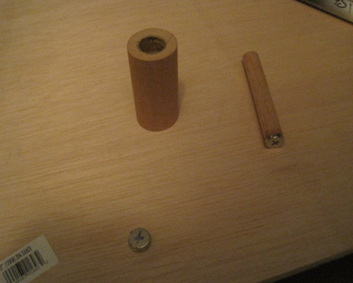
My idea is to change completely the principle of the existing well known (commercial) gage by introducing an intermediate "switching" magnet of very small dimension (I used a little cylindrical magnet 2mm thick and of 5mm diameter). For the two other magnets I used 10 mm high and 5mm diameter magnets.
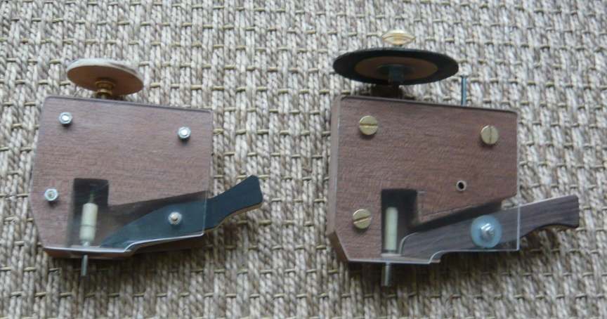
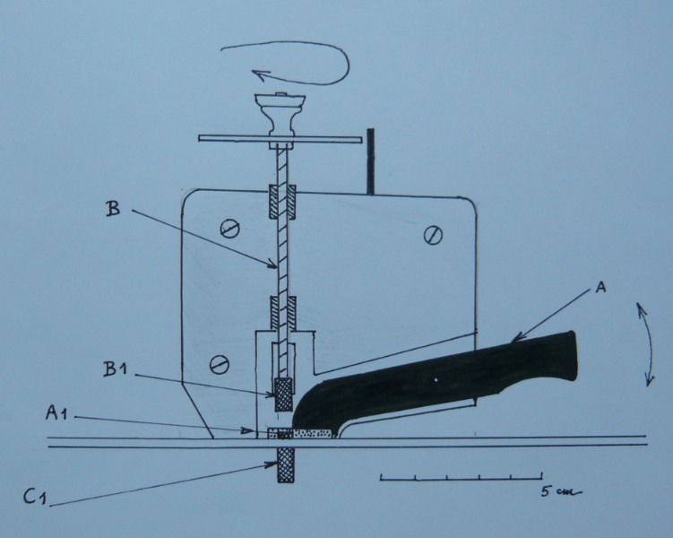
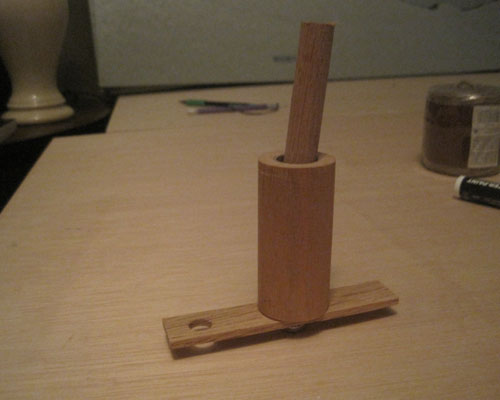
The following plan shows the principle. A photo will show my first realizations in wood. Needlesss to say one could do better with some metal abilities.
The basic sequence is first to make sure the switching magnet starts from full contact with the plate to be measured. You do that by pulling the switching arm up AND by making sure the extracting magnet is sufficiently high when you start.
The trick is to turn the rod holding the extracting magnet to slow its position progressively. At a given precise position you will change the equilibrium of magnetic forces and hear a little click since the switching magnet will leave the position it had in contact with the plate to join the extracting magnet
I have made two prototypes whose difference is only the diameter of the threaded rod (in brass) one is 4 mm and the second one is 3mm thick.
I will try to put on You Tube (IF I CAN
It is not ideal, a bit touchy to operate when you start with it, but you can have the needed precision with some use of it. And it is so much cheaper than the commercal only solution we have.
Needless to say, the real commercial future solution is more I believe in the realm of electronics and more precisely Hall effect sensors (as we could see the topic discussed on this forum some months ago). But for home made cheap realizations, there is still room for this very antique kind of technology. Ah, magnetism.. that is furiously Paris 18 th. century. Ben Franklin, Messmer, and others .
A first photo.
A first plan (front view). B is the extracting threaded rod and B1 the extracting magnet. A1 is the tiny switching magnet. A is the switching rod that rotates around the small white point. And C1 is the internal travelling magnet that you have to introduce in the guitar at the beginning of your measures.
I am ready to answer your questions. And I will be glad to see new improved ideas.
Man, I need a youtube demo so badly!!!!
Barry, I will do my best to provide such a thing... but a WALL exists between my small LUMIX camera and the rest of the world. I know it is a "Quicktime Jpeg" readable file but after that ?????
Does someone know if I can transfer that without fuss to Youtube?
Alain, I had no idea how much a hacklinger gauge costs, and I think it is exorbitantly expensive for what it is.
I can see you've put much thought into this, and I applaud your ingenuity. I understand how it works. Where is the measurement scale? Is it the rod that I see beside the thumbwheel of the extracting rod? Or will it be the position of the lever (switiching rod A) that will indicate the thickness? Right now, I'm not sure that change in mechanism of operation is an improvement over the existing technology, but I haven't seen it work on a video yet.
Hi Bob,
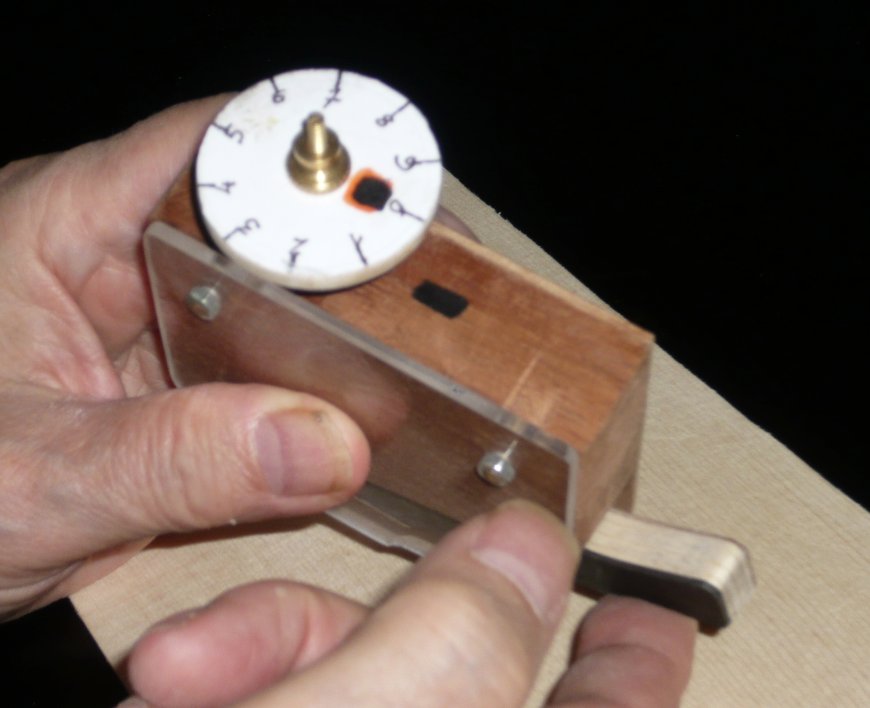
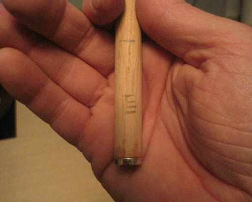
A fifth of the complete 360° rotation i.e. a rotation of 72 ° is worth .1 mm of movement of the magnet. That means two gradations on the shown disk gradation by angles of 36°.(See photo)
And roughly speaking that shows the sensibility of the "thing". You can reach easily a precision less than .1 mm even with this very roughly built prototype... and that is enough for me.
But you better proceed through the use of a wood calibration plate that you have prepared with a tapered thickness. Apparently the nature of the wood does not imply to change the process. I still have to check that thoroughly.
Nota bene: I realize I have not being well inspired in my first post when replacing the expression making "lower" the extracting magnet by erroneously typing to make "slow " the extracting magnet. Sorry for that.
I love the look of the wood, I see no need for metal in such an implement other than for the threaded rod.
I've never used a hacklinger so I'm not sure what happens to the internal magnet when you hit the release point. I really like the idea of capturing the internal magnet onto an adjacent magnet. How easy is it to reset the device for your second measurement? Do you simply lower the graduated, threaded rod back to 0 and press the lever for the internal magnet to pop back to position one?
The Hacklinger gauge does not rely on release. It measures the magnetic force of the internal magnet, which varies with separation. The internal magnet remains in contact with the bottom of whatever is being measured.
Bob,
So you will have to rely on my explanations I fear.
I have no such aim as to beat the existing tool called Hacklinger, just to provide to all another (homemade) solution which does as well.. and costs less.
By the way, no (kolossal, even if only) German patent involved in mine, in spite of my name
Alain,
Your camera may also have come with a free software suite that has video editing capability on the installation CD.
MAYBE?
http://www.dailymotion.com/video/xjtmot_p1010271
Jim, hmm, with respect to the H-gauge, is it a magnet that is concealed within the black plastic, or a ferrous slug that the below-soundboard-magnet senses?
Alain, the differences between languages can be useful; they make me think of possibly difference meanings of the words.
Bob, according the Stew-Mac website:
"A small plastic-coated counter magnet inside the instrument is attracted by a magnet in the base of the gauge."
That is really ingenious. Thank you for sharing it.
Good job, Alain!!
Thanks. My very first prototype (picture here) was made in a couple of hours. It looks ugly, is bigger, but works according to the same principle and as well as the two following ones shown above.
The point that I'd like to improve is the progressive lowering mechanism of the extracting magnet B1. The threaded rod could be replaced by a handier "something"... maybe simply a half of a (Chinese made) cheap Vernier that I could buy for a few Euros on Ebay..
A better craftsman than me could obtain with a Vernier and a few other improvements a better precision than one tenth of a mm.
I really hope some of you will take the idea and start to improve.

Alain, it's as I thought; the wheel on the threaded rod is the readout. I agree that a cheap vernier caliper would be a good substitute for the rod. It would be easier to use and faster too.
So the H-gauge $428 gauge is basically a graduated plastic tube with a neodymium magnet attached to a plunger, that is magnetically coupled to a second magnet that travels along the underside of the plate. I see that the shape of the traveler-magnet is domed so that it can ride over the braces and it's maybe coated with plastic to make it slippery, but other than that it's not exotic. Hmm, the hardware store sells a package of six to eight 8mm dia x 2mm neodymium magnest for $5.
I do not want to criticize the Hacklinger. It was a very good basis for further research and, surprisingly enough for me, this research did not show fastly. I will not emit a too negative judgment about its surprising price. The market of such a tool is ridiculously small, and made (I am told) of pretty affluent violin guys who do not care about this range of price tags.
The handful of hobbyist (like me) interested by antique guitar models could borrow the tool, for the day or two each year it was needed, from a friend .
If the market would be of some amplitude, a small factory would have substituted to this technology something more electronic, hi-tech and interesting. Factory likely located in Asia, and product likely out of the plant for a couple of dollars... then sold in specialized lutherie shops for 99.95 $ or .
But that is only my bet about the things to come and homemade things can have a special appeal to some, even if totally antiquated .
Alain, in your work I see no interference with the H-gauge. Your concept works in a different way than the current product.
Bob,
I also tried to avoid in this design the ultra small internal magnet of the Hacklinger.. that is so nasty when lost on the ground in the middle of saw dust. My internal magnet is bigger and much easier to localize.
In fact, there is a basic shortcoming to this (rather primitive) family of devices (Hacklinger or mine) in terms of precision, it is the relative lack of control that you keep in the alignment between the extracting force and the internal magnet. Whatever you do the internal magnet is always just a little bit off centered. That's life.
But you can reach with some use of them a precision that is sufficient for many kind of applications, including replica's lutherie I think.
If the basic function of these gauges is to measure the change in the field strength above the main magnet as it is being separated from the internal magnet, this could just as easily be done digitally using a linear hall sensor and read-out, i.e. a re-calibrated Gauss meter. I'm going to go and play with this concept downstairs right now.
Sorry to be so dense, but to be clear, the free-floating magnet (FFM) inside the guitar rides along the inside of the soundboard because of the magnetic pull of the lever magnet (LM)---which rides along the outer surface of the soundboard.
As the gauge magnet (GM) gets closer to the LM, its pull becomes greater than that of the FFM, and the LM pivots or rocks up toward the GM.
Correct?
And despite the fact that the LM is no longer in contact with the outer surface of the soundboard, the FFM is still held in place (it doesn't drop off into the box) because... the GM and LM are still close enough to the FFM to keep this from happening?
It's a great idea. If I understand it. Which remains to be seen...
Dennis, that's what I understand, and how it's different than the H-gauge.
Dennis,
If you want to copy it, in Europe you can find the best magnets at "HKCM.de".. but I am sure you have the same kind of suppliers in the US of course. They have the largest choice this side of the Atlantic. And the Euro makes luthiers life really simple
I used spruce for calibration. I have the feeling that such an apparatus would work giving almost the same results whatever the density of the wood, provided it remains in the middle range (perhaps excluding balsa one side and lignum vitae the other side. Am I right or wrong??
Hmm, would there be a problem with ironwood (hee-hee)?
Alain:
Your idea got me thinking (you may want to put some safety glasses on).
Would something like the following work?
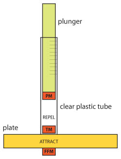
The drawing below includes the same free-floating magnet (FFM) inside the box, but replaces your mechanism with a clear plastic tube that rides along the surface of the plate. The tube has a closed base but is open at the top.
Glued to the base of the tube is a magnet (TM), which is oriented so that it attracts the FFM.
A plunger fits into the tube, and has a magnet (PM) glued to it. The PM is oriented to repel the combined forces of the FFM and the TM.
I'll wait until you stop laughing.
At very first sight, the magnetic field created by the set (FFM+TM), same polarity, will not be affected enough by the small variation of distance between them.
For the third repelling magnet PM will the variation of the thickness of the plate create enough variation of the compound magnetic field of FFM+TM to be discriminant? I do not know but I would tend to doubt.
Very slight disadvantage of using gravity too for the plunger: it imposes if you use weak forces a fixed orientation of your plastic tube.
Just first reactions. I can be totally wrong.
In my contraption the intermediate magnet switches from down to up when the distances between the small switching magnet and the two bigger magnets are roughly equivalent.. almost equal, since wood or void seem to be almost indifferent for the magnetic attractions involved.
BTW, I am glad someone comes with another trick.
Alain:
I found an online calculator, and distilled the following information from it.
This is for grade N42 neodymium disc magnets .25" in diameter x .25" thick:
------Dist. Between Magnets (in)-----
0.079 0.118 0.157 0.197 0.236
------Dist. Between Magnets (mm)-----
2 3 4 5 6
-----------------------------------------------------
Pull Force (lb) 0.21 0.12 0.07 0.05 0.03
Pull Force (oz) 3.36 1.92 1.12 0.80 0.48
Pull Force (g) 95.34 54.48 31.78 22.70 13.62
I'm probably misinterpreting this, but it seems to suggest that there is a measurable difference in force with very little difference in distance.
The "plunger" could be just a length of .25" wooden dowel, and the PM would probably need to be very small, so its force (relative to the TM) wouldn't obliterate the more subtle difference in the additive (and variable) force of FFM + TM.
Ok this is about as rough and dirty as it gets. I hacked together a crude example:
The plunger is a short length of 1/2" dowel rod that I glued a 1/2 x 1/8" magnet to. Total weight = 10 g.
I marked the polarity on all the magnets.
I didn't have any clear plastic tubing, so I used a 1" dia length of dowel with a 5/8" hole bored down to within 1/4" of the bottom.
I used 2 of the same size magnets for my free-floating magnet (FFM).

I recessed the tube magnet (TM) into the bottom of the dowel, again, oriented to attract the FFM, and to repel the plunger magnet (PM).

For plate thicknesses, I used stock that was 1/16, 1/8, 3/16, and 1/4"
And I marked the level that the plunger fell/raised to.
The top mark is just the depth of the tube.
The next 4 marks show where the plunger fell relative to the plates measured.
I have to emphasize how not-so-scientific I was. There was too much slop in the hole bored in the dowel (an extra 1/8"), and so making accurate marks on the dowel was pretty problematic.
Also, there's the thickness of the base of the tube/dowel (1/8" thick), and I didn't play around with different strengths of magnets at the 3 positions.
But again it suggests that blind measurements may be possible.
Finally, sorry about my lousy photos. The only thing I do worse than build guitars is take pictures.
Well, I'm finally starting to catch on...
Dennis, your device, attached to a calibrated dial read-out or vernier could be pretty accurate, it seems to me, and would offer continuous read-out as the device is moved around on the instrument (or whatever) being measured. Hmmmmm...
Dennis, despite your quick-and-dirty assembly (and marking), the main point that impresses me about your design (besides the 6th grade science experiment simplicity) is that the marks on the plunger are surprisingly uniform. I would have expected that progressively thicker material would result in some sort of curve rather than what appears to be linear plotting. That might be the case with thicknesses beyond what would be found in instruments, but this obviously isn't a problem with such strong magnets over short distances. What's more, the marks are practically 1:1 with the material! For every 1/16" change, your gauge shows, what, like 3/32"? With a little experimentation with the materials of the housing, you probably could get a pretty close approximation of actual units.
Congrats Dennis, and welcome to the Club. You took the right decision materializing without delay your contraption. As they said before us "the proof is in the pudding".
I think the two areas to aim at are first the precision of the detection of the thickness. I would believe 1/10th mm (or 1/24 th inch) is the right goal for a start. And the precision of the reading is a goal to keep in mind too.
Doing better than 1/10 th of a mm would be nice but likely not really necessary for replication guitar lutherie.
I'd like to see two other clubs forming. One, a "solenoïd Club" with some fans of simple electromagnetism and simple electric circuits. Two, an "Hall effect Club", self explaining by its title.
Then Debbie could launch a "50$ thickness homemade gauge Challenge"
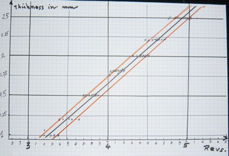
I am leaving for holydays tomorrow morning. Before quitting I'd like to give a look of the general shape of my calibration curves (for the test plank shown in the vidéo).
Horizontal axis: Big lines= Number of revs needed to start measuring. And in light lines increments in tenth of a full rev, as marked upon the disk of the thing.
Vertical axis: Thickness of the plate to be measured in mm.
Pretty linear in fact. The basic spread of results is, my hypothesis, due to the remaining difference of precise centrations between the internal travelling magnet and the switching magnet.
Gives with some repetition something like the tenth of mm (red lines should include a good part of the Gauss curve). But I would like to improve that first prototype to be more precise. Could be difficult with this travelling magnet trick.
Jason: The regularity of the marks had (and still has) me concerned. Look at the table in post #29. It doesn't suggest I'd get the markings I did---all spaced out equally like that.
I ran the "tests" many times, and didn't start to get really discernable differences in the markings until I started shortening the plunger. It started out a couple of inches longer, and weighed around 17g initially. So making the plunger lighter had a pretty pronounced effect.
But there's way too much slop in the mechanism obviously, and one of my fears is that I sort of got the results I was hoping for, if you know what I mean.
I'm probably misreading your chart Alain, but it looks like it says that as the plate material got thicker (creating a weaker pull on the lever magnet), it took more revolutions of the wheel (the traveller magnet had to get closer to the LM) to get your lever magnet to disengage from the FFM?
The thicker the wood plate, the weaker the resistance to extraction of the small switching magnet.. hence the higher the starting position needed.
One feature of this contraption is that you have to start from a position of the extracting magnet that is higher than the click position. Then go down a little to make the final approach, so to speak
Looks complicated, but you get the basic gesture (unbolt, pull up the switch arm to make the switch magnet rejoin the wood plate, rebolt slowly until it clicks) rather easily.
When back from my holydays, I will try to built one with higher precision, specially for mapping the guitar tops thicknesses. But I cannot see how I can progress with the (until now neglected) problem of a better positionning of the travelling inside magnet. The real shortcoming, in terms of precision, of this rather antique magnetic technology I think.
Maybe using an inside system introduced through the soundhole to obtain a very precise localization by new means of the inside magnet.. but I do not see a simple solution for that.
Here's where I am on this.
A couple of years ago I had an idea for a home-made "Hack", but came to a halt trying to find a spring with a spring rate that didn't overpower the whole idea. I still had the parts I was planning to use, and after I got over my confusion about this idea I started working on it again.
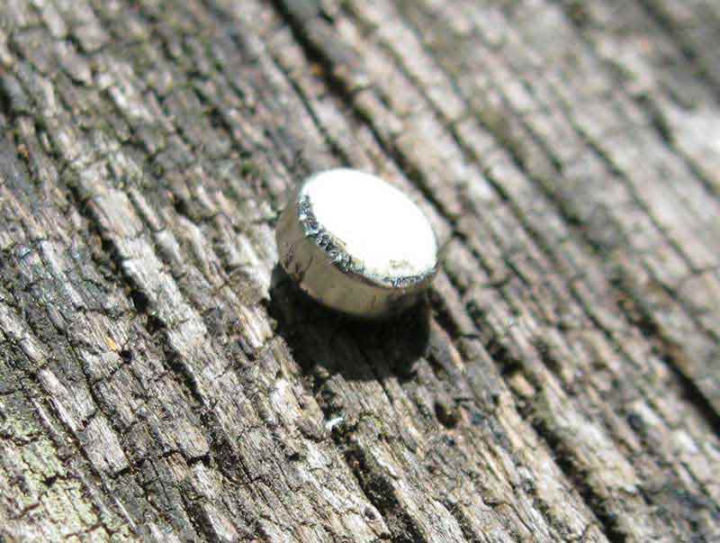
I noticed the cute little magnets that are in the Schatten polarity testers (Stewmac sells them), and the clear plastic tubes they are made from, so I bought a couple. I also got a couple of 1/4" X 1/4" round magnets. Here's the little magnet from inside the polarity tester (with a little bit of stray iron "dust"). The plastic dome is white on one side and black on the other to indicate polarity, but that doesn't matter for this purpose.
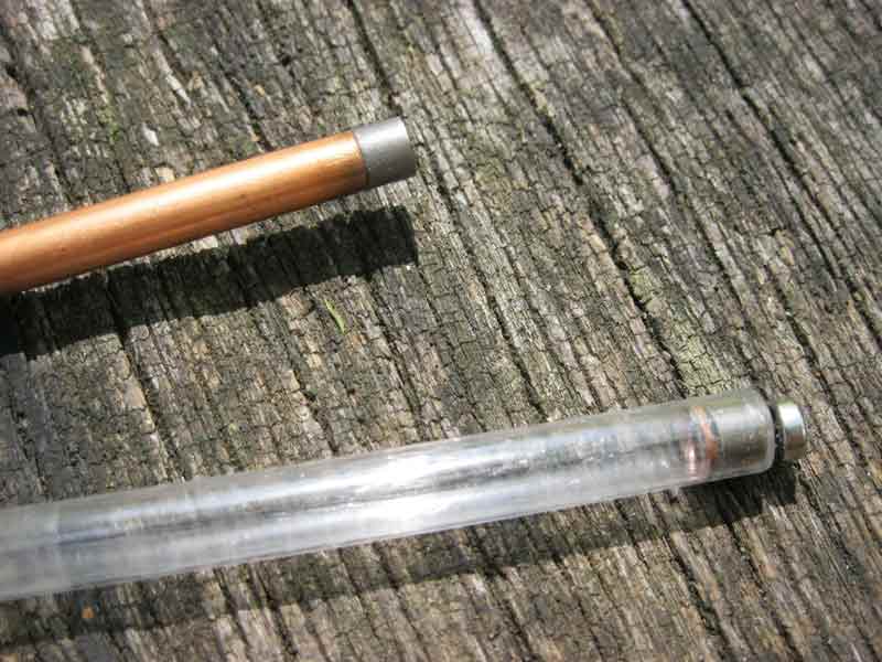
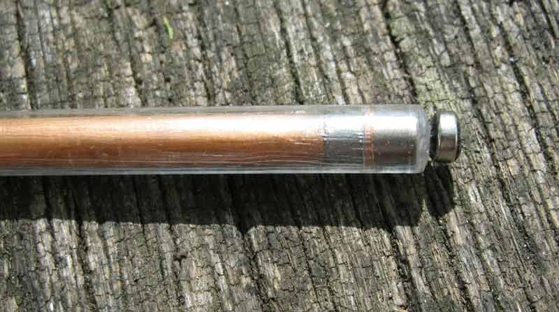
I glued a magnet to a piece of copper tubing that has a 1/4" outside diameter (could be a dowel), and I also flared the end of the same type tubing until it fit tight inside the plastic tube, then cut off a small ring to serve as a stop for the other magnet inside the plastic tube.
It all goes together like this. I've tested this on wood from 1 to 8 mm thick by simply slowly lowering the copper tube (with it's attached magnet), and it's very consistent in "measuring" the thickness, but if I mark the copper tubing at the top of the plastic tubing, the marks are only slightly more than a millimeter apart. By the way, it works very much like a Hacklinger in that there is a click when the magnet separates from the bottom of the plastic tube and hits the stop. It returns to the bottom of the tube when the copper tube is withdrawn, so it doesn't need a trigger to reset it after each use.
Now my mind is working on a lever/dial. I figure that I can make a lever that lowers the copper tube and also serves as a pointer, and on an arc-shaped background behind the lever I can mark calibrated positions. Depending upon the length of the lever and the fulcrum position, I can perhaps get readings accurate to .1 mm at least.
Very cool, John. So you found that your marks were basically as regular relative to the thicknesses of the plates as I found with mine?
Pretty much regular, from zero out to about 6mm, but the millimeter marks were barely over a mm apart so there could be some progression that doesn't show up at that resolution. I'm hoping my lever/dial idea works out or more accuracy.
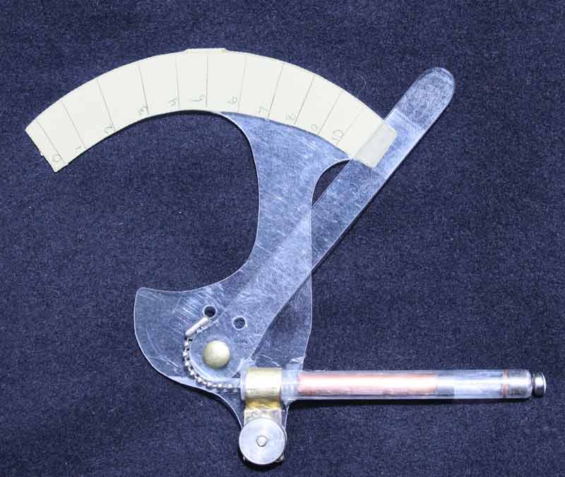
Here's a working prototype, not yet solid enough for particularly good accuracy, but not bad, considering. Looks like I need to lengthen the lever quite a bit to get .1mm accuracy, along with making the while thing more solid. It measures from 0mm to 10mm as it is, but it could easily go above 20mm if the scale was big enough. The whole thing will be bigger than I really wanted it if I lengthen the lever for higher precision, but it looks like it can work.
Now we're cooking with gas.
If you substitute a fine filament for the bead chain, wrapped about a smaller diameter capstan, you could shorten the lever for the same amount of travel. Also, consider a pair of shorter levers in series to give you more precision.
If you use the same kind of magnets as I did (see above) you do not need more than a few mm for the move of your extracting magnet. With some precision in the bearings of your axis, your design could work, I think, quite OK. Interesting variation on a common "three magnets" theme.
A real improvement in precision would require a much better precision in the position of the travelling magnet: But I do not see how it could be done without some more elaborate centration device. Perhaps we should introduce a solenoïd in our devices ??
With an electric current kind of measure we could optimize (maybe??) the position of this invisible magnet.
I've used the device in the picture (still the same, no further work) to check thickness and graduations of some mandolins in the shop (I build and repair mandolins a lot), and it's surprisingly good at giving me a good overall "view" of the thickness to less than .5mm. A little refining and I think I could get in the .1mm ballpark.
By moving the "gauge" around a little, taking several readings and averaging, I can find the internal magnet pretty easily with the gauge and get repeatable fairly accurate thickness measurements.
The extracting magnet itself moves very little, perhaps 12mm to 15mm as the gauge measures from 0mm to 10mm. Eventually, I'll probably come up with a better bearing, a smaller capstan, and a better attachment chain or cable, but it must be calibrated anyway, so eccentricities in the capstan, variations in the chain, and slop in the bearing are automatically compensated for in the calibration process.
My goal is to have it as portable as possible, meaning small and light, no need for electricity. I could then check graduations of instrument in the field in minutes
I am confident you will reach the same kind of precision I get with my contraption, based upon similar basis. Please post your final tool. The little moves are OK to get an almost good idea of where the internal magnet is but I think that introducing a better principle for the precise centration of this important part is needed.
I am hoping someone will do better in the long run with an "Hall effect" apparatus.
I wish I were better in electronic's gadgetry
I thought of you all while at the GAL convention when I saw this thickness gauge made by Mike Doolin, he was showing it at his booth. I had a little talk with him about it, it was quite simple. You can see the measuring marks on the white tape, and the spring was made out of a G guitar string turned on a lathe. For more details you'd probably have to ask Mike yourself, I don't know much else about it!
I had joked with him that you could probably hold someone up with it! "Give me your dough and lookout, I've got a thickness gauge and I KNOW how to use it"...(g)
Thanks Mark,
Looks like the real poor man's Hacklinger, with a zest of Smith and Wesson influence..
If someone is really good at understanding how an "Hall effect" instrument is designed for thickness measures I have noted that Olympus provides such an apparatus called the "Magna Mike 8500" (very likely more expensive than what would be palatable for many of us). A sketch and explanation of what is inside... would be much appreciated by non experts like me.
Interestingly enough, in the States (alas for me), such instruments can be rented through "Advanced Test Equipment Rental". Nice concept for rarely used devices.
Two things to add to my previous infos after more testing of my apparatus (with the threaded rod as figured in the first posts):
1/ I have compared the three versions I completed. They essentially differ by the diameter of the rod. I have one in 5mm diameter, the second in 4mm, and the third in 3mm diameter, so that the vertical move provided by a full revolution of them varies from .8 mm (for the 5 diam.) to .7mm (for the 4mm diam) and .5mm (for the 3mm diam.), respectively.
I thought the 3mm would be superior in precision, but after testing and comparing them, I now think that it is more handy to work with a 4 mm or even 5mm diameter rod. The 3mm rod imposes more rotations and is kind of slow and a bit more confusing in its use.
BTW, if you use non metric rods as certainly you will, I am sure you will find some diameters between 4 and 5 mm... and I think this will be appropriate.
2/ I am quite happy with my choices concerning the extracting magnet and also the small magnet on the switching arm. For the internal travelling magnet, I started with a cylindrical one 5mm diameter and 10 mm high. Now I think this internal magnet has a slight disadvantage if I compare with a weaker magnet. The disadvantage is that it is a little more prone to stay off centered than a smaller and weaker magnet. A problem of lateral friction growing with the pressure of it against a wood plank. I have a better feel of the handling when I use an internal magnet roughly twice weaker than the original i.e. a 5mm diameter and 5 mm high magnet... or two (5 mm diameter and 2 mm high) small magnets just stacked and united by magnetic forces or CA. It seems that they follow better the external magnets.
Well after tightening up my original prototype, I can now safely report that my version of the thickness gauge is of absolutely no value.
That is to say, IF the differences in plate thickness result in a measurable value, my crude effort is not sufficiently sensitive to register it.
But you guys already knew that.
Denis,
including mine and the old Hack of course.
I may have overstated my failure to some extent.
In my second attempt I sized the wooden plunger so that it rode smoothly along the inside of the barrel (the original had a 1/2" plunger rattling around in a 3/8" barrel).
So I no longer had any slop (to speak of) when it came time to mark the plunger's rise and fall as I "measured" different thicknesses of plates.
What I found was that there was no practical difference in the amount of rise and fall of the plunger relative to those thicker and thinner plates.
But there may still be room for improvement.
I haven't been successful in my (casual) attempt to find a small diameter clear plastic tube to replace the wooden barrel in my prototype, or to find something likewise lightweight to serve as the plunger. Replacing the wood components with lightweight alternatives might make the whole thing more responsive.
Also, I haven't been very methodical with respect to the sizes and strengths of the three magnets and how they're configured. I suppose that this could have an influence as well.
Beats me.
Alain:
Are you saying that there is an electrical meter of some sort that can read the strength of a magnetic field?
ok so a little investigative work reveals that (I think I may have a similar previous post) small differences in distance from a magnet result in distinctly measurable gauss values.
For instance, for an N40 disk magnet 1/2" dia x 1/8" thick, the gauss values at increasing distances are:
at a distance of 0" from the magnet = 2,885 gauss
at 1 mm = 2,540
at 2 mm = 2,137
at 3 mm = 1,741
at 4 mm = 1,392
at 5 mm = 1,104
So apparently there is a device that can measure these values, but beats me if it's use (or cost) is practical for this application?
Linear Hall effect sensors will measure magnetic field strength directly, but that is an awfully low field for an accurate measurement. I just checked and the usual sensitivities are in the 1-10 mv/G range, meaning the output signal would be 1-3 to 10-30 mV range. Most analog to digital converters want full scale signals of a couple volts, so the amplifier would have to have a gain of several hundred. That is certainly not outside the realm of possibility, but it might be tricky to make a hobbyist design that is quiet enough. Pair a sensor like this with a Pic microcontroller and you could have meter with built-in non-linearity correction and an attached display or USB connectivity.
Holy Picofarads, Jim. I didn't understand a word of that.
Then you probably want to stick to the wood and plastic kind!
I was an electrical engineer in another lifetime, so this kind of design would almost be trivial, but finding time to work on it is another problem entirely.
For those inclined to switch to electronics, the Honeywell HMC series of detectors should do the trick.
I've used those to measure earth magnetic field strengths, which have a field strength of appx 0.6 Gauss at around 60 deg lat.
With the possible addition of a DC opamp, there's no problem to get 10V of output.
The HMC1001 is a likely candidate in a handable package ( non SMD ). US price should be in the range of 50$+/-
http://www51.honeywell.com/aero/common/documents/myaerospacecatalog-documents/Missiles-Munitions/HMC_1001-1002-1021-1022_Data_Sheet.pdf
I think some form of adjustable calibration against a known thickness will be necesseary, as various woods may influence the measurement, but variations in magnet strength is probably of more concern.
ok I'm officially too stupid for this discussion.
I'm going to go hang out in the glue forum if anyone's looking for me.
Halgeir,
Would you accept being my "project director"? I promise to be a committed, even if not too gifted, student.
I really think the Hack philosophy lacks something for the critical point of a good positionning of its internal magnet.We should explore your component's potential thorougly.
Alain... I'll se if I can dig out some example schematics in the coming days - and I checked the price- it's 20$, but in a min of 5...
I used to build these instruments some years ago, but I don't know if we have any spares left over, as I left the instrument group a few years ago, to take another position in the Co I work for. I probably won't have very much spare time until new year, due to large projects at work and some travellïng.....
You are in France, aren't you???
Halgeir,
I would be ready to invest a little to propose to luthiers a superior thing than this old Hack (or even Hack derived gadgets such as mines). I have received an e-mail from Tim Olsen, a very old pal, who says that R.M. Mottola, another friend, (from the new Savart -web- Journal) is sharing my feeling that it could be done in a palatable way, budget wise... with some luck of course.
Without budget considerations I think the Olympus guys are already proposing a pretty good tool for us, please have a look at this:
http://www.olympus-ims.com/en/magna-mike-8500/
Do you think someone can explain, for the beginner, what's inside?
BTW, all this should remain in a totally "free exchange of info" field too. I am against patenting anything in lutherie... I do not want to look like the old fool who re-invents something that is already present in thousands of other applications, as so often the case
Alain: It looks like the magna mike literally does the task in question without any need for amplifying anything doesn't it? The only remaining question would be the price.
Yes, the big issue seems to really be the price for that kind of tool. But if you live in the US that kind of apparatus can be rented. See my post much above.
What I think would be a "good" DIY version would be of course less performant. A very stable 1/10 th of a mm. precision, without this kind of imprecision and fuss coming from the real position of the internal magnet would be a quite sufficient goal. We need only the basics of the Olympus MM 8500 tool for lutherie. My feeling of course... and the price should remain reasonnable (not like the old Hack )
Some documents are giving good basic info on magnetic field sensors. I found some help from FAQ's given upon the Honeywell specialized site and also an interesting sum of info on a 1998 "Phillips Data Sheet" that you can find Googling on "Magnetic Field sensor NXP". Allegro microsystems Inc. seems to be a specialized firm to consider too for its components.
I also had interesting ideas coming from R.M. Mottola and Tim Olsen. I understand now that we can consider either a totally separate design (ideally a sort of Magna Mike 8500 for the poor fellow) or a design that would take advantage of a personnal computer too, specially for final visualisation of the characteristics of the currents emitted.
Being totally un-expert on that sort of contraption I will not go further on that track, but I do hope someone with better background will explore it in the future.. and report.
Thanks for your inputs and marks of interest anyway.
Over on the music electronics forum we've had some fruitful discussions about Gauss meters and one of the members has designed a very nice pair of calibrated units in kit form that would be overkill for this project.
All one needs really is a DVM and a linear hall sensor that has sufficient range to encompass the max Gauss of the magnet being measured. The hall sensors are only a couple of dollars on ebay. Here's a link to one of the several threads going back a couple of years now.
http://music-electronics-forum.com/t13187/
Thanks, David. Looks interesting as a basis for future work. BTW, could you translate for an electronic-handicapped like me.. what is a DVM?
The centration of the internal magnet, even if plastic coated as they seem to be now on the old Hack (to be slipping laterally a little better I suppose), looks to me as a rather serious deficiency of the original Hack. I also suppose that the little location adjustments we use to do with it, even if without any good control, will be better with a clearer visualisation of magnetic variations, BUT...
Would a replacement of the internal magnet by a little steel ball be possible..as seems to show the Olympus MM 8500 example. Or am I totally wrong?
DVM = digital voltage meter
Thanks Steven.
Just in case someone would follow the "Hall effect" track with the hope to find a way to keep things much more simple and cheap compared with an Olympus Magna Mike 8500 to give an example...Apparently, the first challenge is to be able to avoid the drift of measurements resulting from the simple heating of the sensor being in use...
Now, I am afraid that an Hall sensor derived apparatus cannot be kept very simple, even if our lutherie precision target is not so high. I thank R.M. Mottola from the Savart Journal to have given a good input to my extremely limited knowledge in such topics. I just report what he has gathered for me from good sources.
Apparently, the first challenge is to be able to avoid the drift of measurements resulting from the simple heating of the sensor being in use...
Not at all: http://www.google.com/search?client=safari&rls=en&q=temperature+compensated+linear+hall+effect+sensor&ie=UTF-8&oe=UTF-8
Thanks Andy. I am impressed by the quality of this Micronas firm's (YouTube) publicity, without being able to see if this kind of design is of possible application for our purpose i.e. a reliable distance measure from an internal magnet or steel ball.
I have the vague feeling that proximity measures for many automobile applications are not necessarily of the same nature than the one that would be needed for a Hack/alternative contraption.